U41057-J19-Z146-1-76 July 2004 02–TX150S2–137
Removal/installation routines Conversion of the housing model
© Siemens Nixdorf Informationssysteme AG 1995 Pfad: P:\02-systemeinheiten\TX150S2\TX150S2-e\TX150S2-e.k04
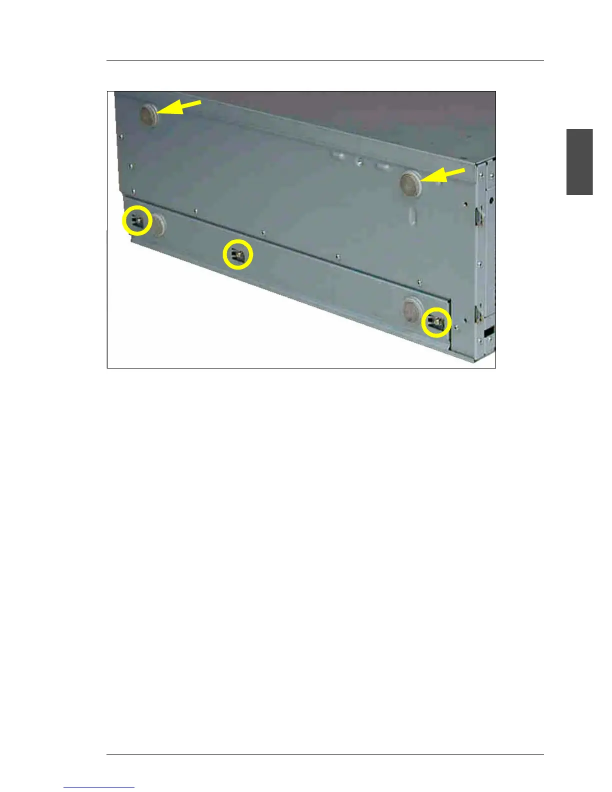
Ê Remove the two upper rubber feet (arrows) on the left side.
Ê Remove the three screws (circles) and take out the rail with the two lower
rubber feet.
The drive cage is designed to make it possible to remove easily the accessible
drives and the operating panel module and remount them with being turned to
the left by 90°.
Ê Remove the 5.25" drives from the drive cage (see page 02-TX150S2-94).
Ê If needed remove the dummy covers.
Ê Pull the operating panel module out of its bay as far as it is possible to unplug
the flat ribbon cable and the USB cable from the operating panel board.
Unplug both cables.
Ê Remove the operating panel module.
 Loading...