CS875-575-375-275-175 Installers Manual with CS5500 keypad B.10.1
Chapter 10: Setting up the CS320
10.1 Overview
The CS320 is an auxiliary power module that can be used with the CSx75 range of panels. It has three programmable
outputs and one dedicated sounder output.
You can use up to eight CS320 auxiliary power modules to supply 32 outputs for the panel, 24 of which are
programmable and eight are dedicated sounder outputs. The 24 programmable outputs can be used as auxiliary power,
fire detector power and sounder power outputs.
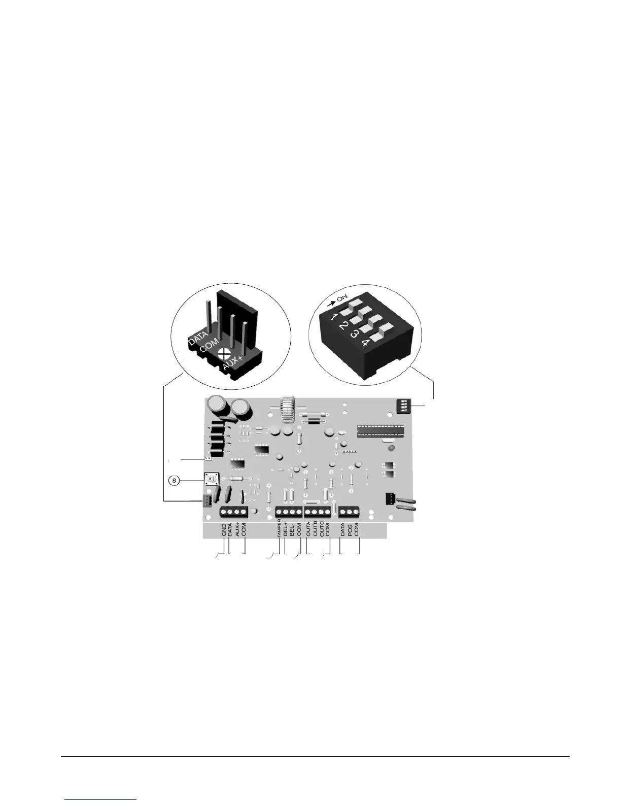
10.2 Installing the CS320 auxiliary power module
Each CS320 auxiliary power module has a tamper terminal that can be used to supervise the casing.
When the CS320 auxiliary power module is connected to the CSx75, the maximum total wire run to all devices is 750
metres. Each CS320 auxiliary power module should be connected individually to the CSx75 and not in series.
.
1
DIP switches
4
Bell
7
Earth
2
Outgoing terminals
5
Tamper terminal
8
Tamper switch (not used)
3
Outputs
6
Incoming bus terminals
9
AC inputs
1
2
3
4
5
6
7
9