CS875-575-375-275-175 Installers Manual with CS5500 keypadB.5.3
3. Set the DIP switch 9 from Table 5-3: RF433 Mhz receiver DIP switches.
4. Power up the RF433 Mhz receiver.
5.2.3 RF433 Mhz receiver status conditions
When you apply power to the CSx75, the middle (red) LED should start blinking. The LEDs on the receiver
indicate the module status.
The red LED at the bottom of the RF433 Mhz receiver may emit a dim glow but is not used as an indicator
and can be ignored.
For information on installing the RF433 Mhz receiver in the various housings, see chapter A-4 Installing a basic
system.
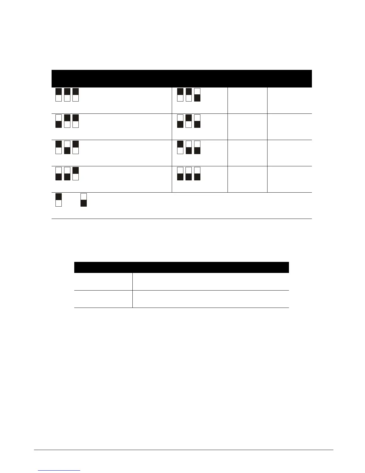
Table 5-3: RF433 Mhz receiver DIP switches
DIP switch 1-3
settings
RF
receiver
Module
number
DIP switch 1-3
settings
RF receiver Module
number
1 34 5 38
233 6 37
3 32 (default) 7 36
4 39 8 35
= ON = OFF DIP switch 4 is not used
Table 5-4: RF433 Mhz receiver LED indications
LED Module Status
Red blinking
Red off
Normal data communication with the CSx75.
No data communication with the CSx75, check the wiring and power source.
Yellow blinking
Yellow off
Receiving radio signals from learn mode wireless sensors.
No radio signals currently being received.