CS875-575-375-275-175 Installers Manual with CS5500 keypad B.15.2
15.2.1 Wiring the CS7050 TCP/IP module
15.2.2 LED indicators
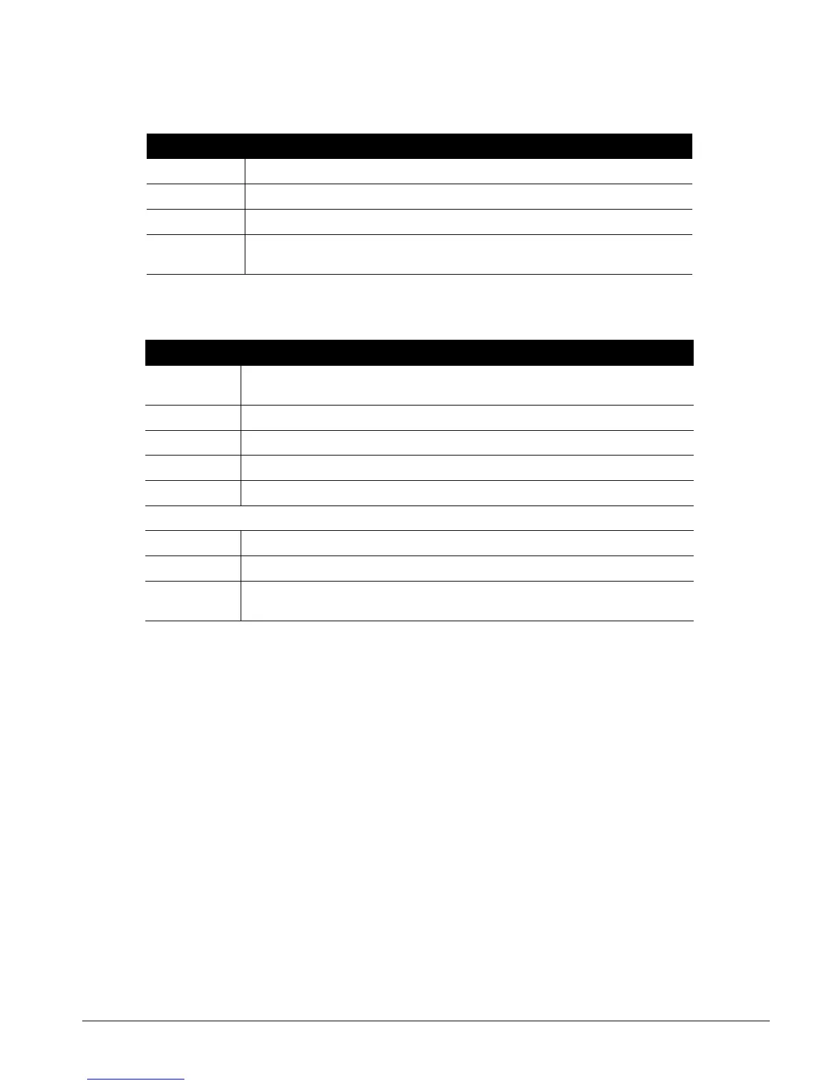
Table 15-1: CS7050 TCP/IP module terminal connections
Terminal Description
+ Connect to the panel bus Aux+.
COM Connect to the panel bus COM terminal.
DATA Connect to the panel bus DATA terminal.
J16
Connect the Ethernet Jack J16 (10BT) to a 10BT Ethernet capable hub, router or gateway. Do not
use a CASCADE or X port in crossover mode.
Table 15-2: CS7050 TCP/IP module LED indicators
LED Description
DS1
Flashes each time the CS7050 has an opportunity to access the Aritech CSx75 bus. It should flash
about twice a second.
DS3 Flashes when it is waiting for a communication from the Ethernet module.
DS4 On when waiting for a reply from a Aritech CSx75 bus device.
DS5 Flashes when the CS7050 gets a packet from the Ethernet module.
DS6 On when the bus has a message to send to the network.
DS3 - DS6 are off if the system is initialized, normal and waiting for a new event to report.
L1 (on SIM module) Flashes ON Ethernet Activity.
L2 (on SIM module) Steady ON when Ethernet Link is established with the 10BT cable.
DS2
The sixth LED is located toward the back of the board. It is used for hardware, and only glows dimly
when connected to the CSx75 control panel.