CS875-575-375-275-175 Installers Manual with CS5500 keypadB.10.2
10.2.1 Wiring the CS320 auxiliary power module
10.2.2 Setting the DIP switches
DIP switches 1-3 set the address of the CS320 auxiliary power module.
DIP switch 4 controls the tamper feature. On enables tamper. Off disables tamper.
Table 10-1: CS320 auxiliary power module terminal connections
Terminal Description
DATA
Connect to the KP DATA terminal of the CSx75. This terminal is the incoming data-
signalling terminal to the CS320 auxiliary power module.
COM
Connect to the KP COM terminal of the CSx75. This terminal supplies the common side of
the power to the CS320 auxiliary power module.
POS Connect to the KP POS terminal of the CSx75.
DATA This terminal is the outgoing data-signalling terminal for the bus extension.
COM Common terminal for any device powered by the CS320 auxiliary power module.
OUT A Programmable output current limited to 1.9 A.
1
1.The total current of the CS320 auxiliary power module is 2.5 A. There can be a total
of 1.9 A between outputs A, B and C and a total of 2.5 A between the sounders and
outputs.
OUT B Programmable output current limited to 1.9 A.
COM Common terminal for any device powered by the CS320 auxiliary power module.
OUT C Programmable output current limited to 1.9 A.
BELL + Positive sounder current limited to 2.5 A.
BELL - Negative sounder current limited to 2.5 A.
TAM
Optional tamper terminal. Connect the normally closed tamper switch between this terminal
and COM. If DIP switch 4 is off, this feature is not used.
EARTH (GND) Earth Ground
AC AC input. Connect to a 16.5 V 50 VA transformer.
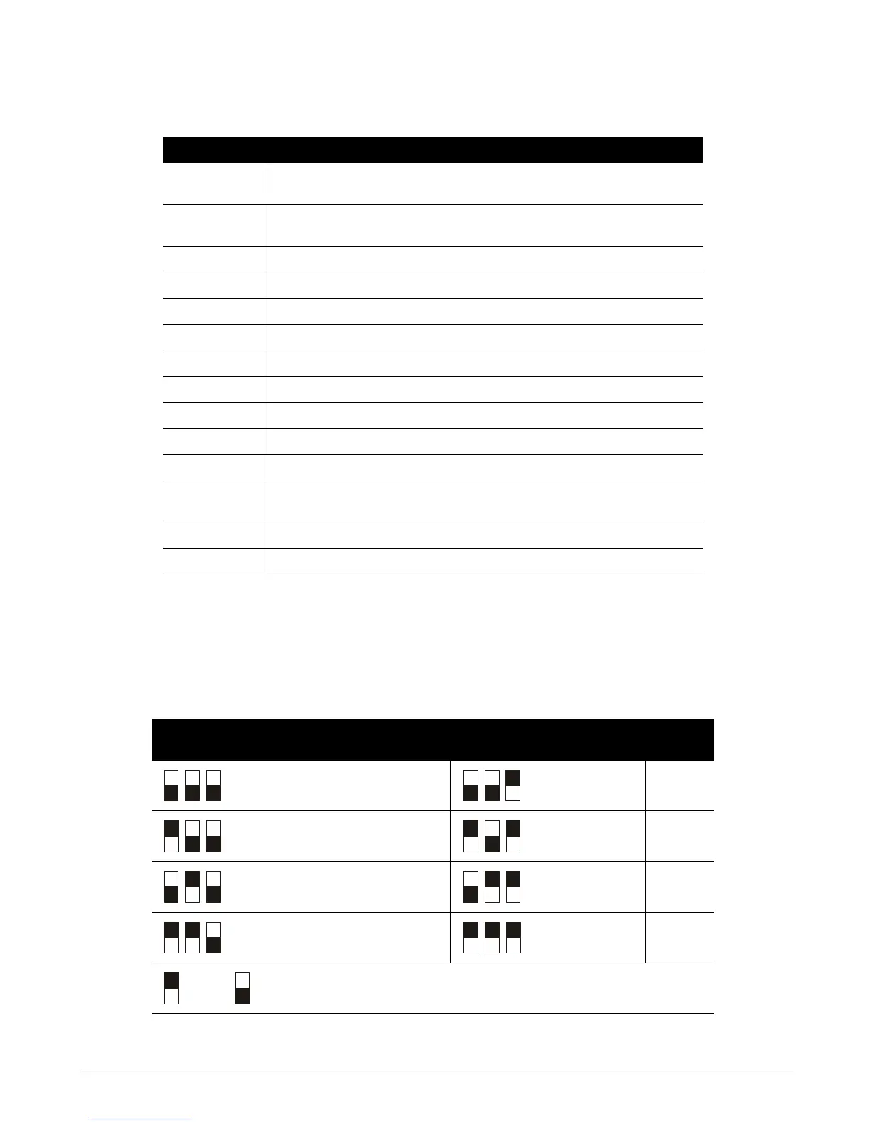
Table 10-2: CS320 auxiliary power module DIP switches
DIP switch 1-3 settings Address DIP switch 1-3
settings
Address
84
88
85
89
86
90
87
91
= ON = OFF