GE Power Management 269Plus Motor Management Relay 3-
55
3 SETUP AND USE OVERLOAD CURVE SETPOINTS
3
3.20 OVERLOAD CURVE SETPOINTS
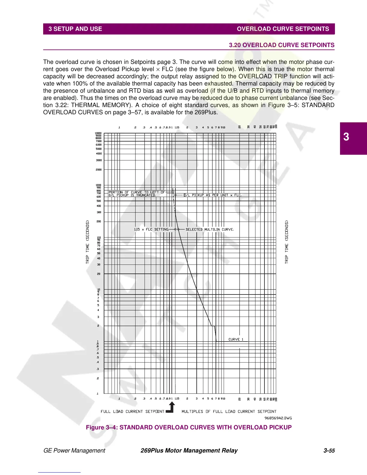
The overload curve is chosen in Setpoints page 3. The curve will come into effect when the motor phase cur-
rent goes over the Overload Pickup level × FLC (see the figure below). When this is true the motor thermal
capacity will be decreased accordingly; the output relay assigned to the OVERLOAD TRIP function will acti-
vate when 100% of the available thermal capacity has been exhausted. Thermal capacity may be reduced by
the presence of unbalance and RTD bias as well as overload (if the U/B and RTD inputs to thermal memory
are enabled). Thus the times on the overload curve may be reduced due to phase current unbalance (see Sec-
tion 3.22: THERMAL MEMORY). A choice of eight standard curves, as shown in Figure 3–5: STANDARD
OVERLOAD CURVES on page 3–57, is available for the 269Plus.
Figure 3–4: STANDARD OVERLOAD CURVES WITH OVERLOAD PICKUP