GE Power Management 269Plus Motor Management Relay 3-
59
3 SETUP AND USE THERMAL CAPACITY ALARM
3
3.21 THERMAL CAPACITY ALARM
The Thermal Capacity Alarm setpoint level determines the threshold that thermal capacity must equal or
exceed for an alarm condition to exist. The time delay set determines the amount of time that these conditions
must persist before an actual alarm occurs.
3.22 THERMAL MEMORY
The 269Plus uses an internal thermal memory register to represent the thermal capacity of the motor. To "fill"
this register, the square of the equivalent motor heating current is integrated over time. This equivalent current
is a biased average of the 3 phase currents. The biasing factor is derived from the amount of negative-
sequence current flowing into the motor if the U/B Input to TC is enabled. The rate at which the memory fills is
thus dependent on the amount of overload, the unbalance present, as well as the RTD bias. The RTD bias can
be defeated in Setpoints page 5. When the thermal memory register fills to a value corresponding to 100%
motor thermal capacity used, an OVERLOAD TRIP will be initiated. This value is determined from the overload
curve.
Thermal memory is emptied in certain situations. If the motor is in a stopped state the memory will discharge
within the
MOTOR STOPPED COOL TIME
(factory value = 30 minutes). If the motor is running at less than full load,
thermal memory will discharge at a programmed rate to a certain value. This value is determined by the
FLC
THERMAL CAPACITY REDUCTION
setpoint. For example, a value of 25% may be chosen for this setpoint. If the
current being drawn by the motor drops below full load current to 80%, then the thermal memory will empty to
80% of the
FLC THERMAL CAPACITY REDUCTION
setpoint, namely, 20% (0.8 × 25%). In this way the thermal mem-
ory will discharge to an amount related to the present motor current in order to represent the actual tempera-
ture of the motor closely. Thermal memory will discharge at the correct rate, in an exponential fashion, even if
control power is removed from the 269Plus.
Thermal memory can be cleared to 0% by using the Emergency Restart feature (see Section 3.23: EMER-
GENCY RESTART on page 3–63).
If the phase current is between 1.00 × FLC and the Overload Pickup level × FLC, one of two thermal model
algorithms can be observed. If the
THERMAL CAPACITY USED
is less than the phase current (as a multiple of
FLC) × the FLC Thermal Capacity Reduction setpoint, the
THERMAL CAPACITY USED
will rise to that value. If, on
the other hand, the
THERMAL CAPACITY USED
is above that value, it will remain unchanged (neither increase nor
decrease) unless RTD BIAS is enabled, in which case the greater of the two values will be used.
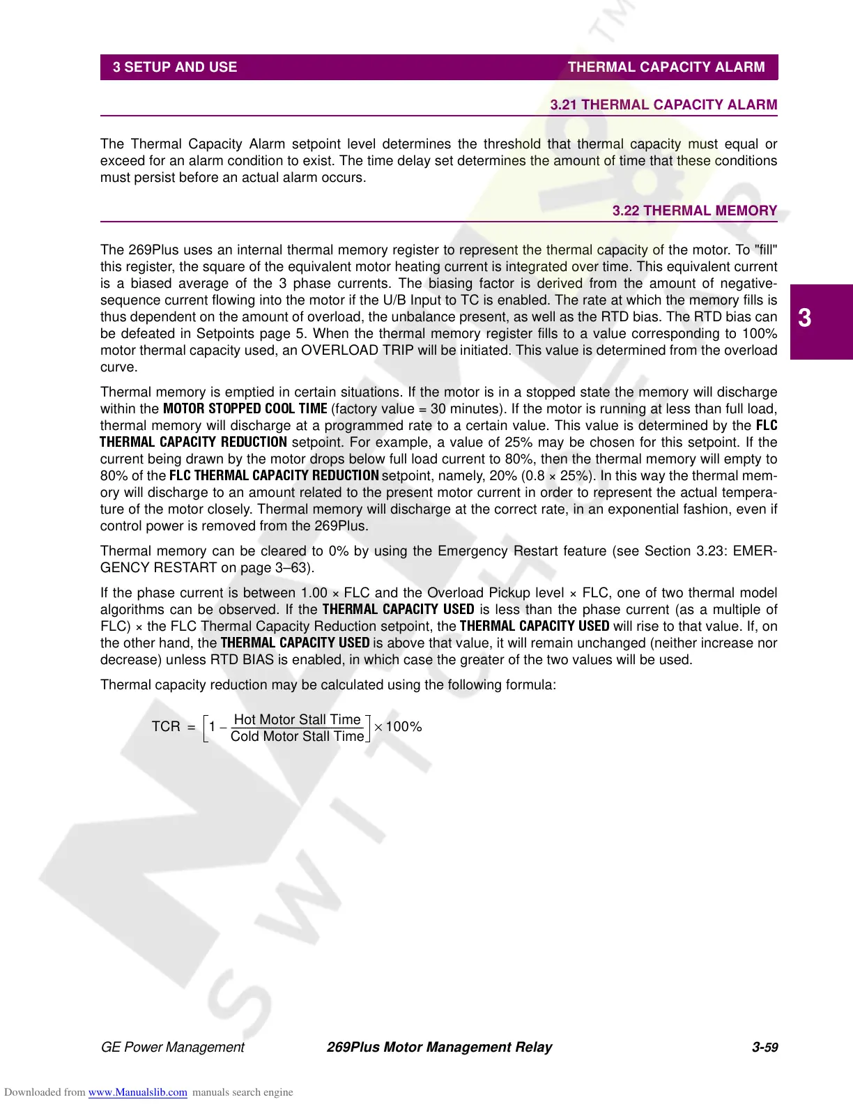
Thermal capacity reduction may be calculated using the following formula:
TCR 1
Hot Motor Stall Time
Cold Motor Stall Time
---------------------------------------------------------
– 100%×=