GE Power Management 269Plus Motor Management Relay 8-
3
8 269PC SOFTWARE HARDWARE CONFIGURATION
8
8.5 HARDWARE CONFIGURATION
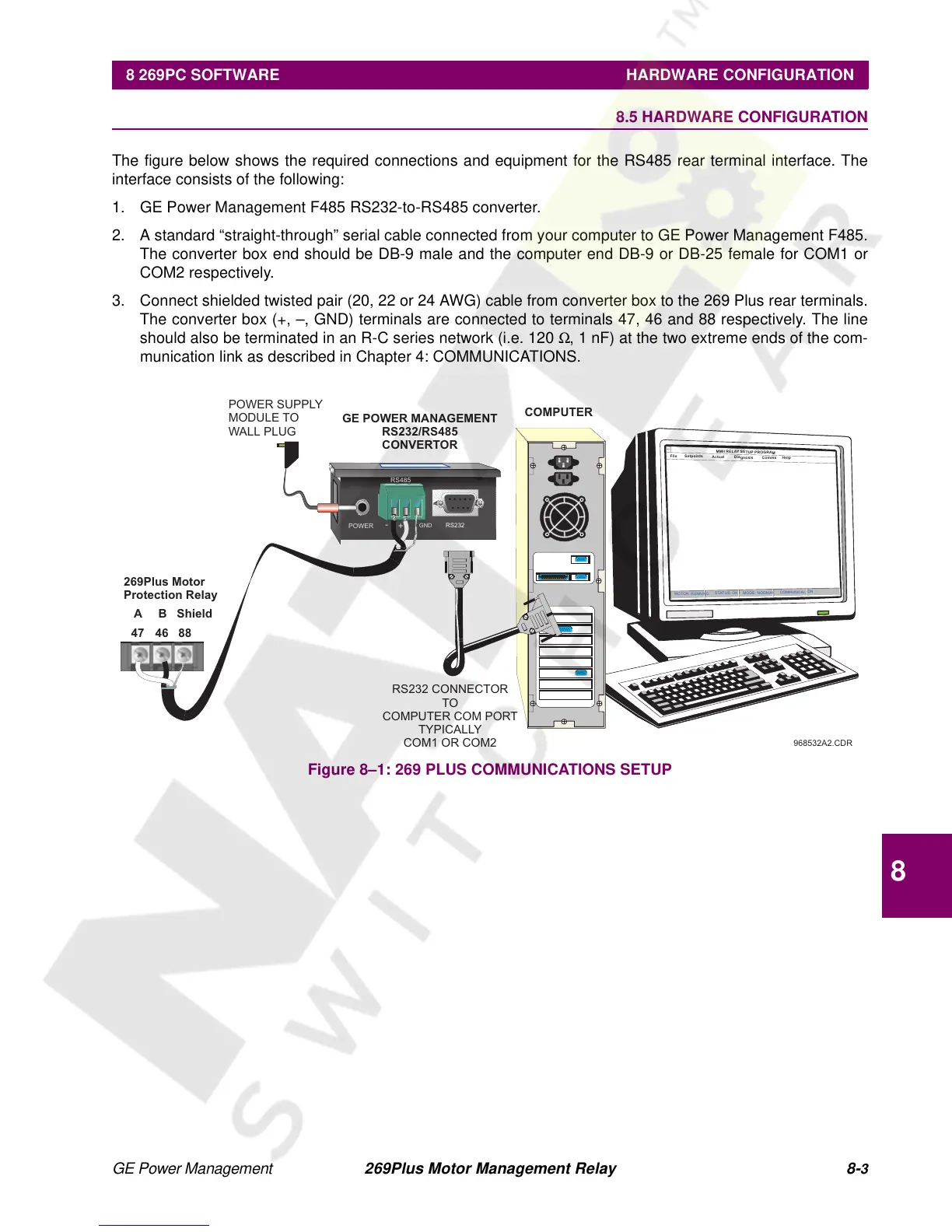
The figure below shows the required connections and equipment for the RS485 rear terminal interface. The
interface consists of the following:
1. GE Power Management F485 RS232-to-RS485 converter.
2. A standard “straight-through” serial cable connected from your computer to GE Power Management F485.
The converter box end should be DB-9 male and the computer end DB-9 or DB-25 female for COM1 or
COM2 respectively.
3. Connect shielded twisted pair (20, 22 or 24 AWG) cable from converter box to the 269 Plus rear terminals.
The converter box (+, –, GND) terminals are connected to terminals 47, 46 and 88 respectively. The line
should also be terminated in an R-C series network (i.e. 120 Ω, 1 nF) at the two extreme ends of the com-
munication link as described in Chapter 4: COMMUNICATIONS.
Figure 8–1: 269 PLUS COMMUNICATIONS SETUP
968532A2.CDR
M
M
II R
E
L
A
Y
S
E
T
U
P
P
R
O
G
R
A
M
F
ile
S
e
tp
o
in
t
s
A
c
tu
al
D
ia
g
n
o
s
is
C
o
m
m
s
H
e
lp
M
O
T
O
R
:R
U
N
N
IN
G
S
T
A
T
U
S
:O
K
M
O
D
E
:N
O
R
M
A
L
C
O
M
M
U
N
IC
A
L
:
O
N
+
GND
RS485
RS232
-
POWER
GE POWER MANAGEMENT
RS232/RS485
CONVERTOR
COMPUTER
POWER SUPPLY
MODULE TO
WALL PLUG
RS232 CONNECTOR
TO
COMPUTER COM PORT
TYPICALLY
COM1 OR COM2
269Plus Motor
Protection Relay
Shield
88
A
47
B
46