4-
24
269Plus Motor Management Relay GE Power Management
FORMAT CODES 4 COMMUNICATIONS
4
4.10 FORMAT CODES
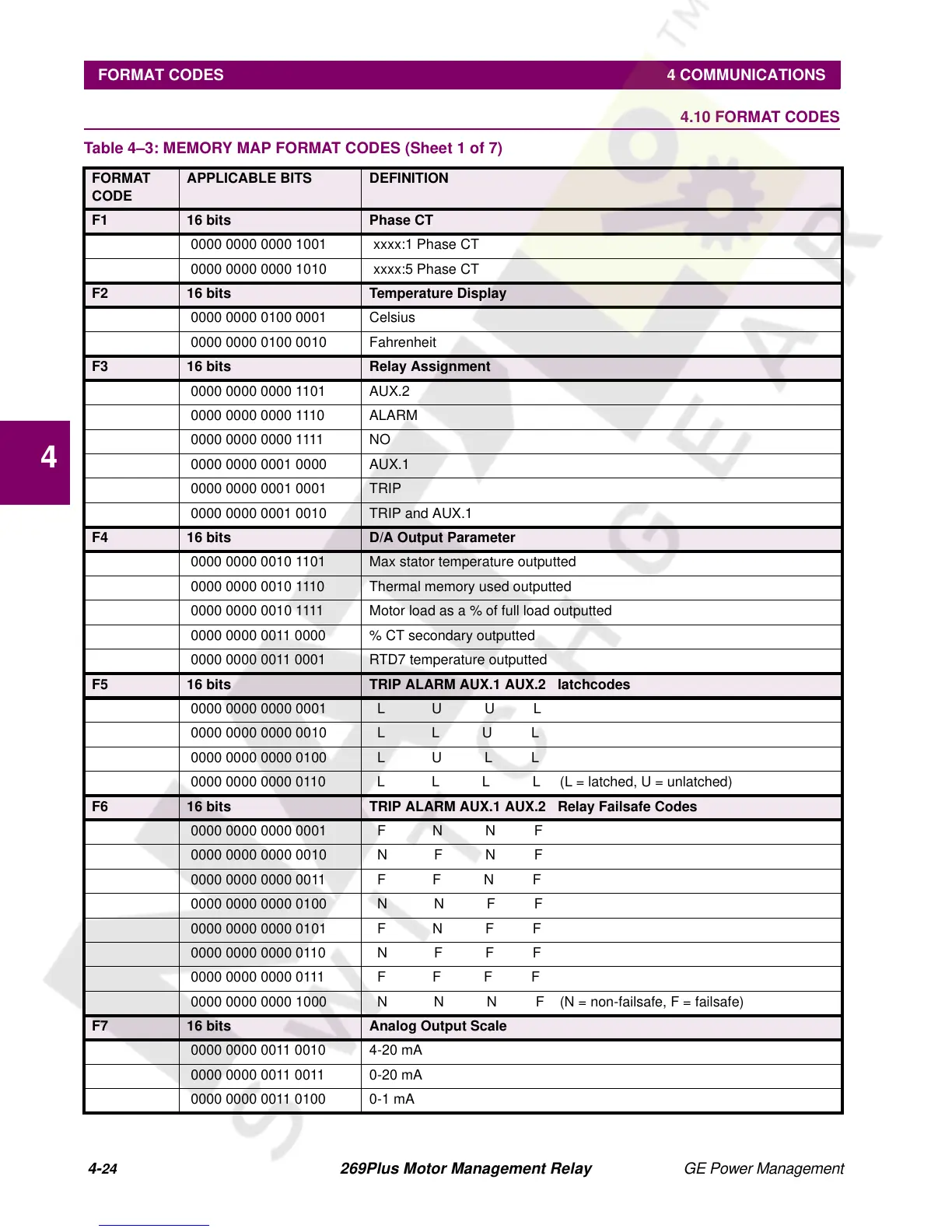
Table 4–3: MEMORY MAP FORMAT CODES (Sheet 1 of 7)
FORMAT
CODE
APPLICABLE BITS DEFINITION
F1 16 bits Phase CT
0000 0000 0000 1001 xxxx:1 Phase CT
0000 0000 0000 1010 xxxx:5 Phase CT
F2 16 bits Temperature Display
0000 0000 0100 0001 Celsius
0000 0000 0100 0010 Fahrenheit
F3 16 bits Relay Assignment
0000 0000 0000 1101 AUX.2
0000 0000 0000 1110 ALARM
0000 0000 0000 1111 NO
0000 0000 0001 0000 AUX.1
0000 0000 0001 0001 TRIP
0000 0000 0001 0010 TRIP and AUX.1
F4 16 bits D/A Output Parameter
0000 0000 0010 1101 Max stator temperature outputted
0000 0000 0010 1110 Thermal memory used outputted
0000 0000 0010 1111 Motor load as a % of full load outputted
0000 0000 0011 0000 % CT secondary outputted
0000 0000 0011 0001 RTD7 temperature outputted
F5 16 bits TRIP ALARM AUX.1 AUX.2 latchcodes
0000 0000 0000 0001 L U U L
0000 0000 0000 0010 L L U L
0000 0000 0000 0100 L U L L
0000 0000 0000 0110 L L L L (L = latched, U = unlatched)
F6 16 bits TRIP ALARM AUX.1 AUX.2 Relay Failsafe Codes
0000 0000 0000 0001 F N N F
0000 0000 0000 0010 N F N F
0000 0000 0000 0011 F F N F
0000 0000 0000 0100 N N F F
0000 0000 0000 0101 F N F F
0000 0000 0000 0110 N F F F
0000 0000 0000 0111 F F F F
0000 0000 0000 1000 N N N F (N = non-failsafe, F = failsafe)
F7 16 bits Analog Output Scale
0000 0000 0011 0010 4-20 mA
0000 0000 0011 0011 0-20 mA
0000 0000 0011 0100 0-1 mA