GE Power Management 269Plus Motor Management Relay 2-
31
2 INSTALLATION METER OPTION INSTALLATION
2
f) SERIAL COMMUNICATIONS PORT (COM1 - 46,47,48)
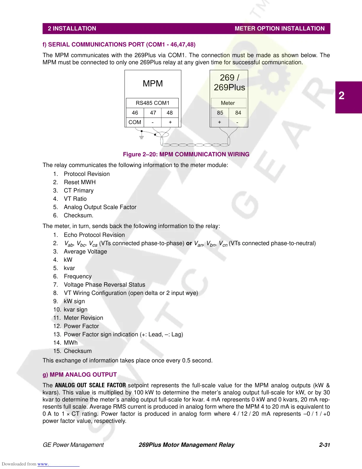
The MPM communicates with the 269Plus via COM1. The connection must be made as shown below. The
MPM must be connected to only one 269Plus relay at any given time for successful communication.
Figure 2–20: MPM COMMUNICATION WIRING
The relay communicates the following information to the meter module:
1. Protocol Revision
2. Reset MWH
3. CT Primary
4. VT Ratio
5. Analog Output Scale Factor
6. Checksum.
The meter, in turn, sends back the following information to the relay:
1. Echo Protocol Revision
2.
V
ab
,
V
bc
,
V
ca
(VTs connected phase-to-phase) or
V
an
,
V
bn
,
V
cn
(VTs connected phase-to-neutral)
3. Average Voltage
4. kW
5. kvar
6. Frequency
7. Voltage Phase Reversal Status
8. VT Wiring Configuration (open delta or 2 input wye)
9. kW sign
10. kvar sign
11. Meter Revision
12. Power Factor
13. Power Factor sign indication (+: Lead, –: Lag)
14. MWh
15. Checksum
This exchange of information takes place once every 0.5 second.
g) MPM ANALOG OUTPUT
The
ANALOG OUT SCALE FACTOR
setpoint represents the full-scale value for the MPM analog outputs (kW &
kvars). This value is multiplied by 100 kW to determine the meter’s analog output full-scale for kW, or by 30
kvar to determine the meter’s analog output full-scale for kvar. 4 mA represents 0 kW and 0 kvars, 20 mA rep-
resents full scale. Average RMS current is produced in analog form where the MPM 4 to 20 mA is equivalent to
0 A to 1 × CT rating. Power factor is produced in analog form where 4 / 12 / 20 mA represents –0 / 1 / +0
power factor value, respectively.
MPM
46 47 48
COM - +
RS485 COM1
269 /
269Plus
85 84
+-
Meter