3-
6
269Plus Motor Management Relay GE Power Management
RELAY DISPLAY MODES 3 SETUP AND USE
3
3.3 RELAY DISPLAY MODES
The 269Plus display is used for viewing actual motor values, setpoint values, HELP messages, and TRIP/
ALARM messages. This is accomplished by having the relay in one of four possible modes of operation:
1. ACTUAL VALUES mode
2. SETPOINTS mode
3. HELP mode
4. TRIP/ALARM mode
The relay operates correctly, giving full motor protection, regardless of which display mode is in effect. The dif-
ferent modes affect only the data that appears on the 48-character alphanumeric display.
The TRIP/ALARM mode can only be entered by having one or more of the trip or alarm level setpoints
exceeded. The other display modes can be entered using the ACTUAL VALUES, SET POINTS, or HELP keys
(see Section 3.2: CONTROLS AND INDICATORS on page 3–2).
The ACTUAL VALUES and SETPOINTS modes are based on a book-like system of "pages" and "lines". One
line from any page may be displayed at any given time. To "turn" a page, the [PAGE s] and [PAGE t]keys
are used. To scan the lines on a page the [LINE s]andLINEt] keys are used. In the HELP and TRIP/
ALARM modes only the [LINE s] and [LINE t] keys are needed.
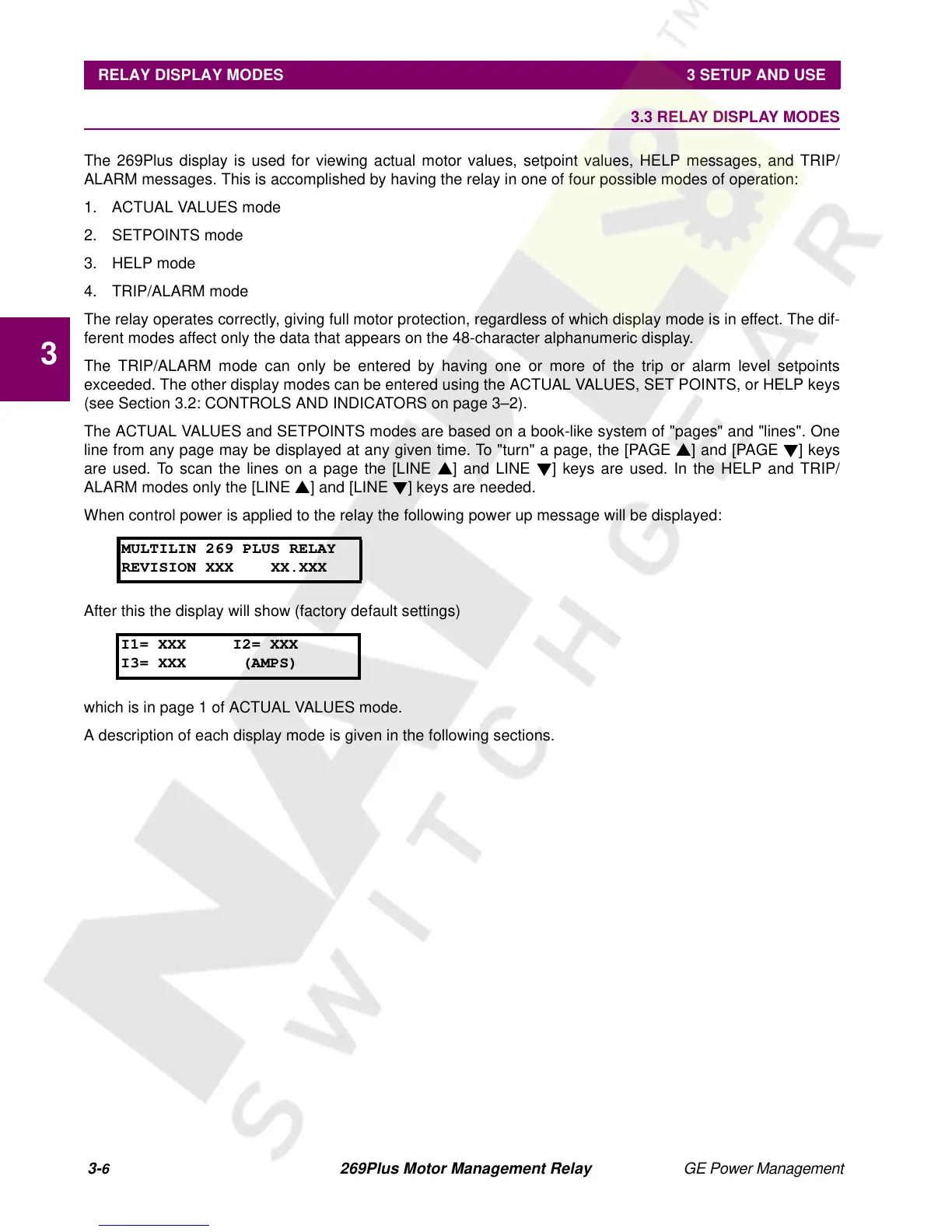
When control power is applied to the relay the following power up message will be displayed:
After this the display will show (factory default settings)
which is in page 1 of ACTUAL VALUES mode.
A description of each display mode is given in the following sections.
MULTILIN 269 PLUS RELAY
REVISION XXX XX.XXX
I1= XXX I2= XXX
I3= XXX (AMPS)