GE Power Management 269Plus Motor Management Relay 2-
19
2 INSTALLATION AUXILIARY RELAY #2 CONTACTS
2
2.10 AUXILIARY RELAY #2 CONTACTS
This relay provides another set of NO/NC contacts with the same ratings as the other relays (on a drawout ver-
sion of 269Plus, only one set of AUX. 2 contacts is available and the user must specify normally open or nor-
mally closed when ordering). This relay is different from the others in the fact that it is permanently
programmed as latched and fail-safe.
This relay may be programmed to activate on any combination of alarm conditions (see STARTS/HOUR
TIMER on page 3–15 for factory preset configurations). The feature assignment programming is thus the same
as for the Alarm relay.
Connections to the relay contacts are made via a terminal block which uses #6 screws.
The rear of the 269Plus relay shows output relay contacts in their power down state. Figures 2–7:
RELAY WIRING DIAGRAM (AC CONTROL POWER), 2–9: RELAY WIRING DIAGRAM (TWO
PHASE CTs), and 2–10: RELAY WIRING DIAGRAM (DC CONTROL POWER) show output relay
contacts with power applied, no trips or alarms, and Factory Configurations in effect (i.e. TRIP: fail-
safe, ALARM: non-fail-safe, AUX.1: non-fail-safe, AUX.2: fail-safe). See Figure 2–8: OUTPUT
RELAY CONTACT STATES on page 2–9 for a list of all possible contact states.
2.11 RTD SENSOR CONNECTIONS
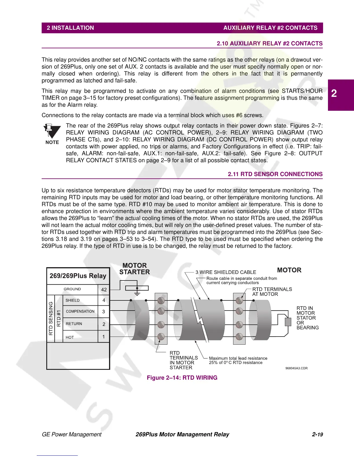
Up to six resistance temperature detectors (RTDs) may be used for motor stator temperature monitoring. The
remaining RTD inputs may be used for motor and load bearing, or other temperature monitoring functions. All
RTDs must be of the same type. RTD #10 may be used to monitor ambient air temperature. This is done to
enhance protection in environments where the ambient temperature varies considerably. Use of stator RTDs
allows the 269Plus to “learn” the actual cooling times of the motor. When no stator RTDs are used, the 269Plus
will not learn the actual motor cooling times, but will rely on the user-defined preset values. The number of sta-
tor RTDs used together with RTD trip and alarm temperatures must be programmed into the 269Plus (see Sec-
tions 3.18 and 3.19 on pages 3–53 to 3–54). The RTD type to be used must be specified when ordering the
269Plus relay. If the type of RTD in use is to be changed, the relay must be returned to the factory.
Figure 2–14: RTD WIRING
NOTE