GE Power Management 269Plus Motor Management Relay 3-
61
3 SETUP AND USE THERMAL MEMORY
3
b) RTD INPUT TO THERMAL MEMORY
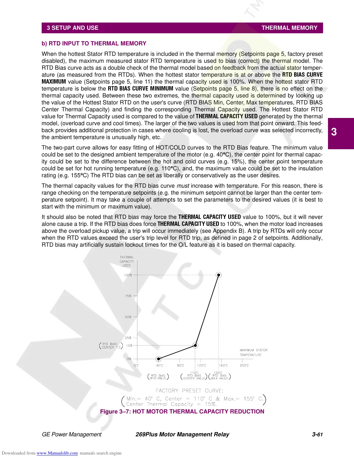
When the hottest Stator RTD temperature is included in the thermal memory (Setpoints page 5, factory preset
disabled), the maximum measured stator RTD temperature is used to bias (correct) the thermal model. The
RTD Bias curve acts as a double check of the thermal model based on feedback from the actual stator temper-
ature (as measured from the RTDs). When the hottest stator temperature is at or above the
RTD BIAS CURVE
MAXIMUM
value (Setpoints page 5, line 11) the thermal capacity used is 100%. When the hottest stator RTD
temperature is below the
RTD BIAS CURVE MINIMUM
value (Setpoints page 5, line 8), there is no effect on the
thermal capacity used. Between these two extremes, the thermal capacity used is determined by looking up
the value of the Hottest Stator RTD on the user's curve (RTD BIAS Min, Center, Max temperatures, RTD BIAS
Center Thermal Capacity) and finding the corresponding Thermal Capacity used. The Hottest Stator RTD
value for Thermal Capacity used is compared to the value of
THERMAL CAPACITY USED
generated by the thermal
model, (overload curve and cool times). The larger of the two values is used from that point onward. This feed-
back provides additional protection in cases where cooling is lost, the overload curve was selected incorrectly,
the ambient temperature is unusually high, etc.
The two-part curve allows for easy fitting of HOT/COLD curves to the RTD Bias feature. The minimum value
could be set to the designed ambient temperature of the motor (e.g. 40°
°°
°C), the center point for thermal capac-
ity could be set to the difference between the hot and cold curves (e.g. 15%), the center point temperature
could be set for hot running temperature (e.g. 110°
°°
°C), and, the maximum value could be set to the insulation
rating (e.g. 155°
°°
°C) The RTD bias can be set as liberally or conservatively as the user desires.
The thermal capacity values for the RTD bias curve
must
increase with temperature. For this reason, there is
range checking on the temperature setpoints (e.g. the minimum setpoint cannot be larger than the center tem-
perature setpoint). It may take a couple of attempts to set the parameters to the desired values (it is best to
start with the minimum or maximum value).
It should also be noted that RTD bias may force the
THERMAL CAPACITY USED
value to 100%, but it will never
alone cause a trip. If the RTD bias does force
THERMAL CAPACITY USED
to 100%, when the motor load increases
above the overload pickup value, a trip will occur immediately (see Appendix B). A trip by RTDs will only occur
when the RTD values exceed the user's trip level for RTD trip, as defined in page 2 of setpoints. Additionally,
RTD bias may artificially sustain lockout times for the O/L feature as it is based on thermal capacity.
Figure 3–7: HOT MOTOR THERMAL CAPACITY REDUCTION