GE Power Management 269Plus Motor Management Relay C-
3
C RTD CIRCUITRY TWO-WIRE RTD LEAD COMPENSATION
C
C.3 TWO-WIRE RTD LEAD COMPENSATION
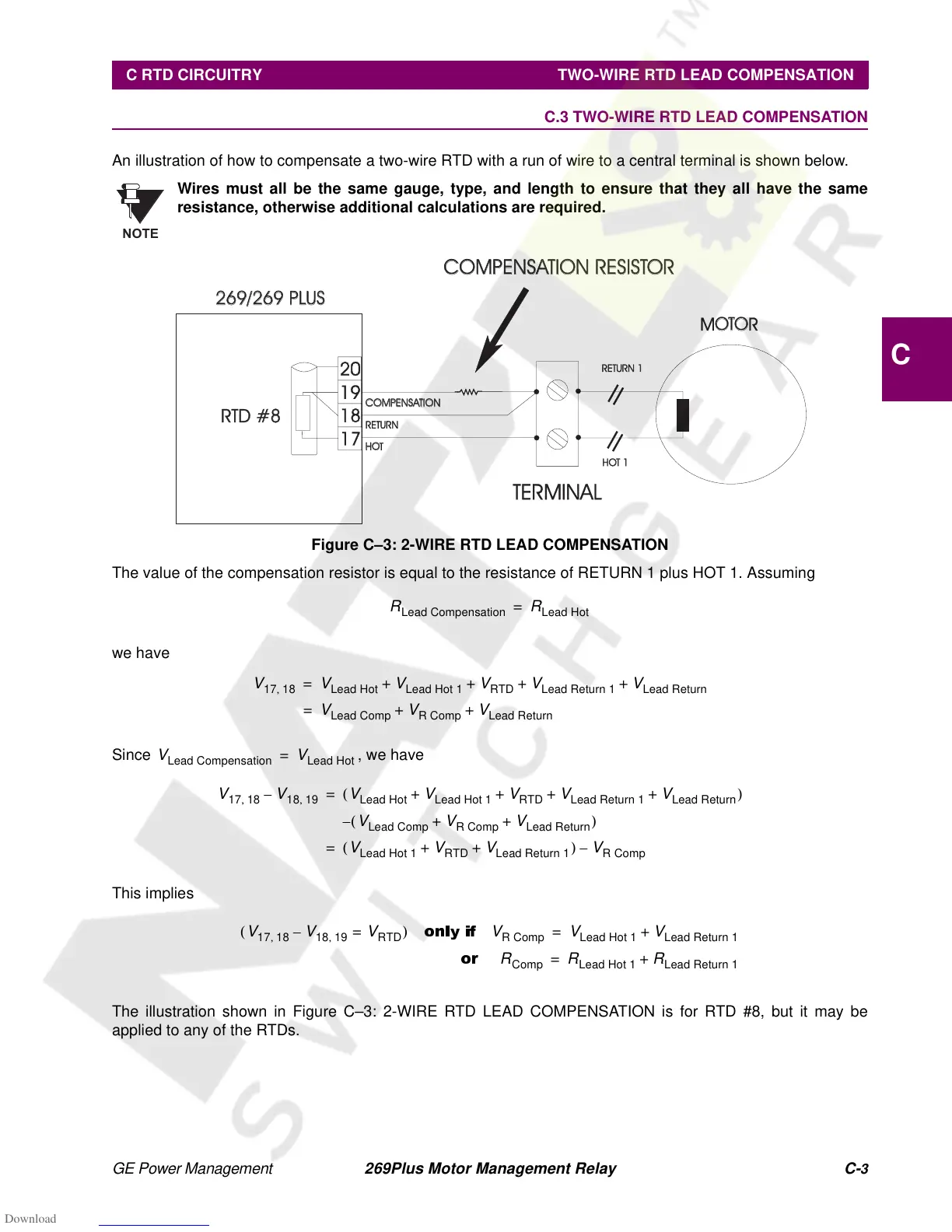
An illustration of how to compensate a two-wire RTD with a run of wire to a central terminal is shown below.
Wires must all be the same gauge, type, and length to ensure that they all have the same
resistance, otherwise additional calculations are required.
Figure C–3: 2-WIRE RTD LEAD COMPENSATION
The value of the compensation resistor is equal to the resistance of RETURN 1 plus HOT 1. Assuming
we have
Since , we have
This implies
The illustration shown in Figure C–3: 2-WIRE RTD LEAD COMPENSATION is for RTD #8, but it may be
applied to any of the RTDs.
NOTE
20
19
18
17
RTD #8RTD #8
269/269 PLUS269/269
PLUS
MOTOOTOR
=
=
COMPENSATION RESISTORCOMPENSATION RESISTOR
COMPENSACOMPENSATIONTION
RETURN
HOHOT
RETURN 1RETURN
1
HOT 1HOT
1
TERMINAL
R
Lead Compensation
R
Lead Hot
=
V
17 18
,
V
Lead Hot
V
Lead Hot 1
V
RTD
V
Lead Return 1
V
Lead Return
+++ +=
V
Lead Comp
V
RComp
V
Lead Return
++=
V
Lead Compensation
V
Lead Hot
=
V
17 18
,
V
18 19
,
–
V
Lead Hot
V
Lead Hot 1
V
RTD
V
Lead Return 1
V
Lead Return
+++ +()=
V
Lead Comp
V
RComp
V
Lead Return
++()–
V
Lead Hot 1
V
RTD
V
Lead Return 1
++()
V
RComp
–=
V
17 18
,
V
18 19
,
–
V
RTD
=()
only if
V
RComp
V
Lead Hot 1
V
Lead Return 1
+=
or
R
Comp
R
Lead Hot 1
R
Lead Return 1
+=