GE Power Management 269Plus Motor Management Relay 1-
5
1 INTRODUCTION ORDER CODE / INFORMATION
1
1.4 ORDER CODE / INFORMATION
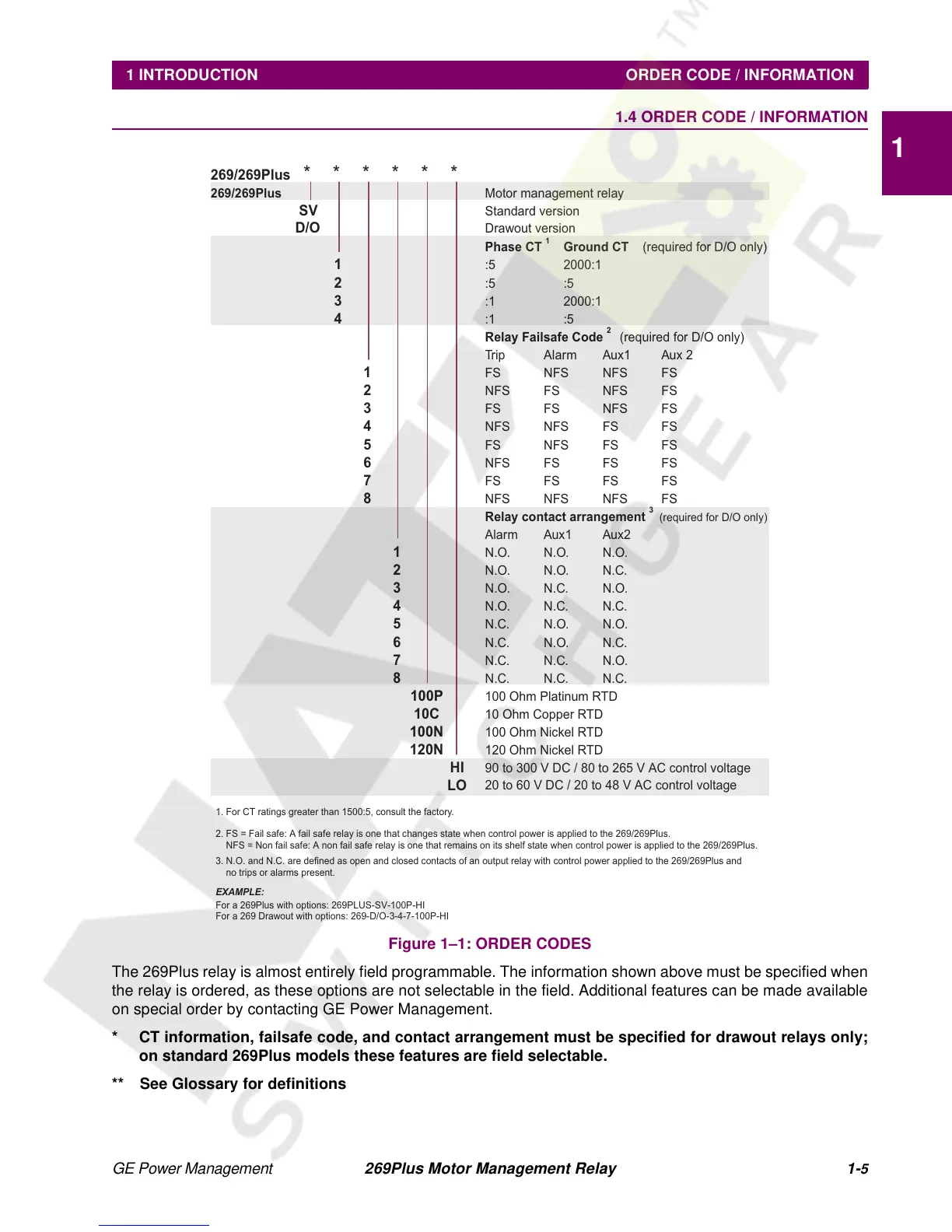
Figure 1–1: ORDER CODES
The 269Plus relay is almost entirely field programmable. The information shown above must be specified when
the relay is ordered, as these options are not selectable in the field. Additional features can be made available
on special order by contacting GE Power Management.
* CT information, failsafe code, and contact arrangement must be specified for drawout relays only;
on standard 269Plus models these features are field selectable.
** See Glossary for definitions
269/269Plus
******
269/269Plus
Motor management relay
SV
Standard version
D/O
Drawout version
Phase CT
1
Ground CT
(required for D/O only)
1
:5 2000:1
2
:5 :5
3
:1 2000:1
4
:1 :5
Relay Failsafe Code
2
(required for D/O only)
Trip Alarm Aux1 Aux 2
1
FS NFS NFS FS
2
NFS FS NFS FS
3
FS FS NFS FS
4
NFS NFS FS FS
5
FS NFS FS FS
6
NFS FS FS FS
7
FS FS FS FS
8
NFS NFS NFS FS
Relay contact arrangement
3
(required for D/O only)
Alarm Aux1 Aux2
1
N.O. N.O. N.O.
2
N.O. N.O. N.C.
3
N.O. N.C. N.O.
4
N.O. N.C. N.C.
5
N.C. N.O. N.O.
6
N.C. N.O. N.C.
7
N.C. N.C. N.O.
8
N.C. N.C. N.C.
100P
100 Ohm Platinum RTD
10C
10 Ohm Copper RTD
100N
100 Ohm Nickel RTD
120N
120 Ohm Nickel RTD
HI
LO
90 to 300 V DC / 80 to 265 V AC control voltage
20 to 60 V DC / 20 to 48 V AC control voltage
1. For CT ratings greater than 1500:5, consult the factory..
2. FS = Fail safe: A fail safe relay is one that changes state when control power is applied to the 269/269Plus.
NFS = Non fail safe: A non fail safe relay is one that remains on its shelf state when control power is applied to the 269/269Plus.
3. N.O. and N.C. are defined as open and closed contacts of an output relay with control power applied to the 269/269Plus and
no trips or alarms present.
EXAMPLE:
For a 269Plus with options: 269PLUS-SV-100P-HI
For a 269 Drawout with options: 269-D/O-3-4-7-100P-HI