GE Power Management 269Plus Motor Management Relay D-
1
D TWO PHASE CT CONFIGURATION DESCRIPTION
D
APPENDIX DD TWO PHASE CT CONFIGURATION D.1 DESCRIPTION
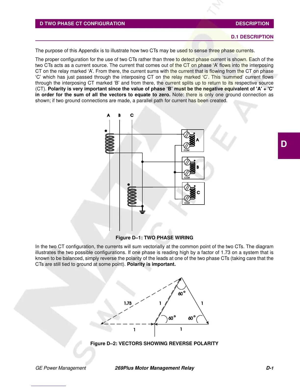
The purpose of this Appendix is to illustrate how two CTs may be used to sense three phase currents.
The proper configuration for the use of two CTs rather than three to detect phase current is shown. Each of the
two CTs acts as a current source. The current that comes out of the CT on phase ‘A’ flows into the interposing
CT on the relay marked ‘A’. From there, the current sums with the current that is flowing from the CT on phase
‘C’ which has just passed through the interposing CT on the relay marked ‘C’. This ‘summed’ current flows
through the interposing CT marked ‘B’ and from there, the current splits up to return to its respective source
(CT). Polarity is very important since the value of phase ‘B’ must be the negative equivalent of 'A' + 'C'
in order for the sum of all the vectors to equate to zero. Note: there is only one ground connection as
shown; if two ground connections are made, a parallel path for current has been created.
Figure D–1: TWO PHASE WIRING
In the two CT configuration, the currents will sum vectorially at the common point of the two CTs. The diagram
illustrates the two possible configurations. If one phase is reading high by a factor of 1.73 on a system that is
known to be balanced, simply reverse the polarity of the leads at one of the two phase CTs (taking care that the
CTs are still tied to ground at some point). Polarity is important.
Figure D–2: VECTORS SHOWING REVERSE POLARITY
A
B
C
A B
C
:5
:5
:5
:COM:COM
:COM:COM
:COM:COM