D-
2
269Plus Motor Management Relay GE Power Management
DESCRIPTION D TWO PHASE CT CONFIGURATION
D
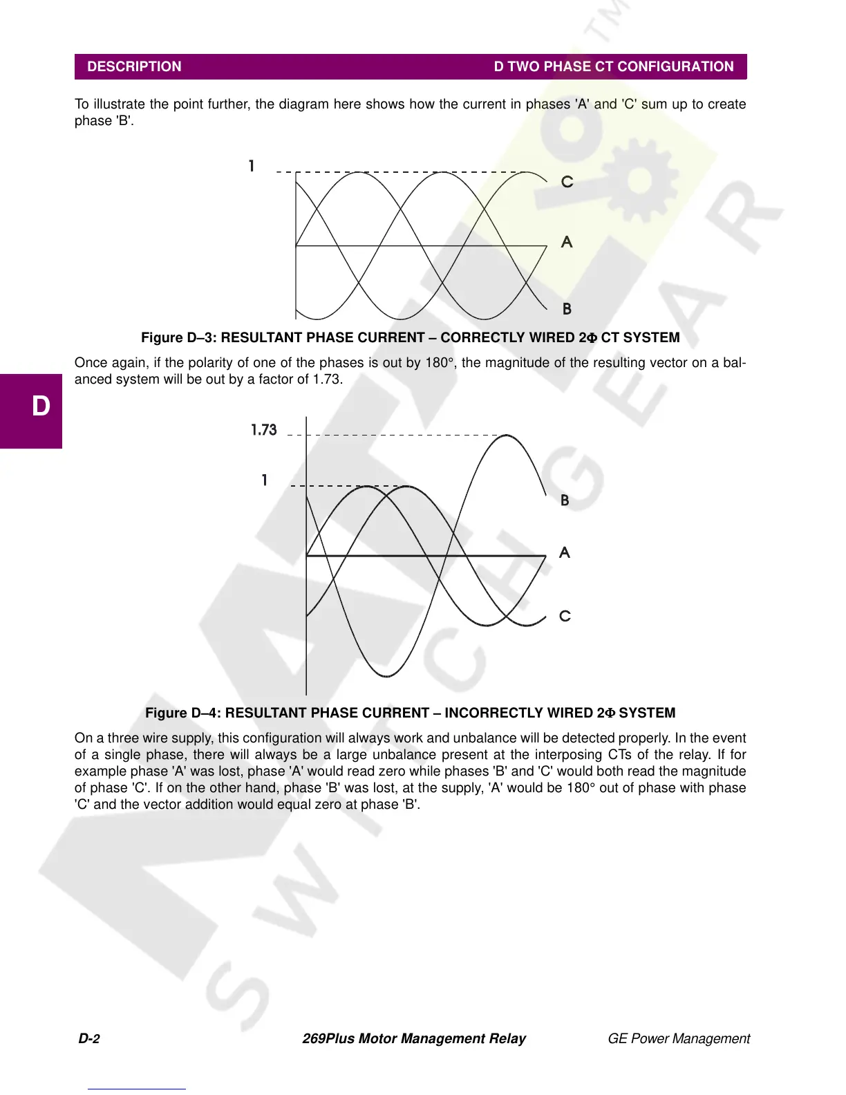
To illustrate the point further, the diagram here shows how the current in phases 'A' and 'C' sum up to create
phase 'B'.
Figure D–3: RESULTANT PHASE CURRENT – CORRECTLY WIRED 2Φ
ΦΦ
Φ CT SYSTEM
Once again, if the polarity of one of the phases is out by 180°, the magnitude of the resulting vector on a bal-
anced system will be out by a factor of 1.73.
Figure D–4: RESULTANT PHASE CURRENT – INCORRECTLY WIRED 2Φ
ΦΦ
Φ SYSTEM
On a three wire supply, this configuration will always work and unbalance will be detected properly. In the event
of a single phase, there will always be a large unbalance present at the interposing CTs of the relay. If for
example phase 'A' was lost, phase 'A' would read zero while phases 'B' and 'C' would both read the magnitude
of phase 'C'. If on the other hand, phase 'B' was lost, at the supply, 'A' would be 180° out of phase with phase
'C' and the vector addition would equal zero at phase 'B'.