4-
6
269Plus Motor Management Relay GE Power Management
SUPPORTED FUNCTIONS 4 COMMUNICATIONS
4
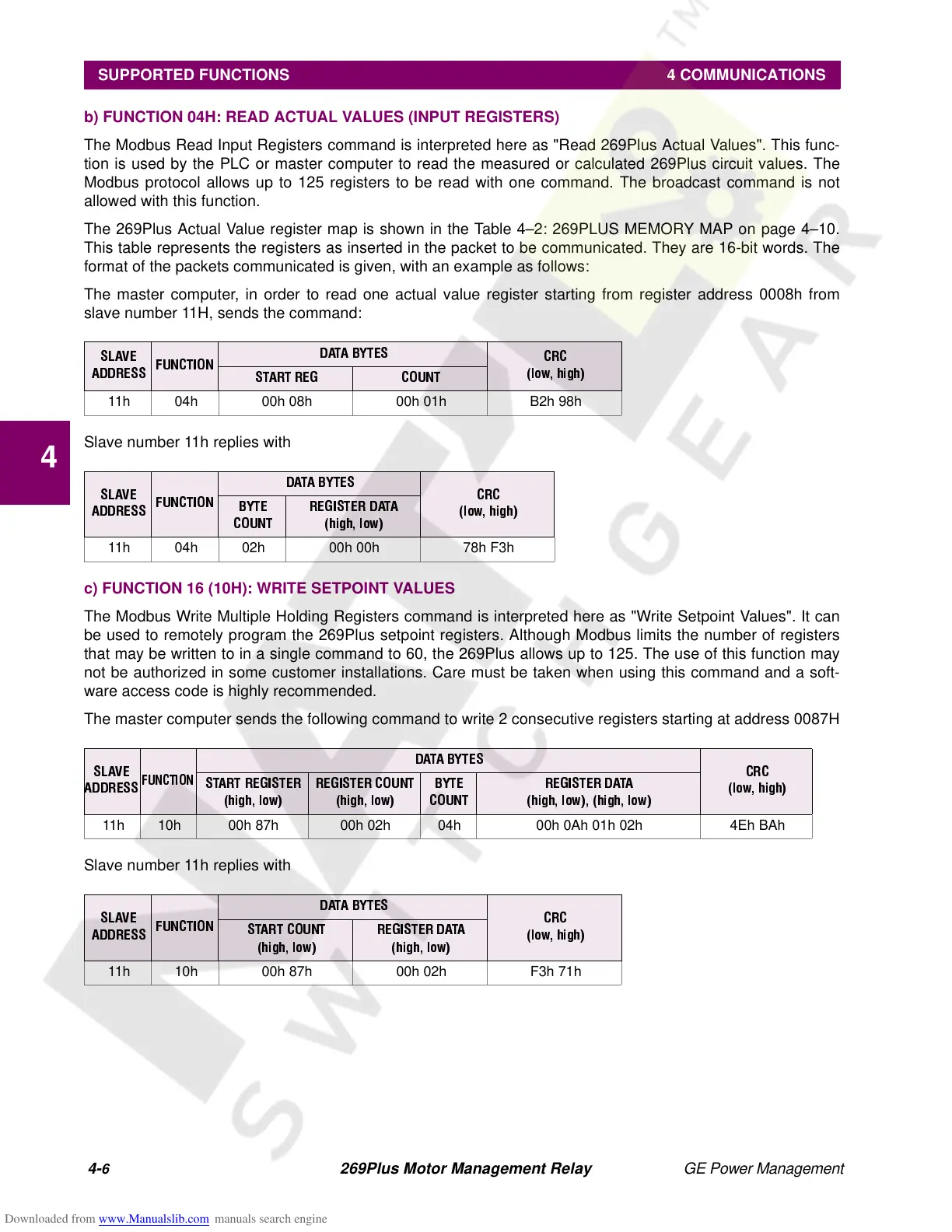
b) FUNCTION 04H: READ ACTUAL VALUES (INPUT REGISTERS)
The Modbus Read Input Registers command is interpreted here as "Read 269Plus Actual Values". This func-
tion is used by the PLC or master computer to read the measured or calculated 269Plus circuit values. The
Modbus protocol allows up to 125 registers to be read with one command. The broadcast command is not
allowed with this function.
The 269Plus Actual Value register map is shown in the Table 4–2: 269PLUS MEMORY MAP on page 4–10.
This table represents the registers as inserted in the packet to be communicated. They are 16-bit words. The
format of the packets communicated is given, with an example as follows:
The master computer, in order to read one actual value register starting from register address 0008h from
slave number 11H, sends the command:
Slave number 11h replies with
c) FUNCTION 16 (10H): WRITE SETPOINT VALUES
The Modbus Write Multiple Holding Registers command is interpreted here as "Write Setpoint Values". It can
be used to remotely program the 269Plus setpoint registers. Although Modbus limits the number of registers
that may be written to in a single command to 60, the 269Plus allows up to 125. The use of this function may
not be authorized in some customer installations. Care must be taken when using this command and a soft-
ware access code is highly recommended.
The master computer sends the following command to write 2 consecutive registers starting at address 0087H
Slave number 11h replies with
SLAVE
ADDRESS
FUNCTION
DATA BYTES
CRC
(low, high)
START REG COUNT
11h 04h 00h 08h 00h 01h B2h 98h
SLAVE
ADDRESS
FUNCTION
DATA BYTES
CRC
(low, high)
BYTE
COUNT
REGISTER DATA
(high, low)
11h 04h 02h 00h 00h 78h F3h
SLAVE
ADDRESS
FUNCTION
DATA BYTES
CRC
(low, high)
START REGISTER
(high, low)
REGISTER COUNT
(high, low)
BYTE
COUNT
REGISTER DATA
(high, low), (high, low)
11h 10h 00h 87h 00h 02h 04h 00h 0Ah 01h 02h 4Eh BAh
SLAVE
ADDRESS
FUNCTION
DATA BYTES
CRC
(low, high)
START COUNT
(high, low)
REGISTER DATA
(high, low)
11h 10h 00h 87h 00h 02h F3h 71h