GE Power Management 269Plus Motor Management Relay 4-
5
4 COMMUNICATIONS SUPPORTED FUNCTIONS
4
4.6 SUPPORTED FUNCTIONS
The following functions are supported:
• 03 Read Relay Setpoint Registers.
• 04 Read Relay Actual Values.
• 16 (10h) Write Relay Setpoints.
These functions are described in detail as follows:
a) FUNCTION 03h: READ SETPOINTS (HOLDING REGISTERS)
The Modbus Read Holding Registers command is interpreted here as "Read 269Plus Setpoints". It is used by
the master computer to program the relaying parameters. Up to 125 consecutive registers (250 bytes) can be
read with one command. The broadcast command is not allowed with this function.
The 269 Plus Motor Protection Setpoint Register map is given in the Memory Map. This table represents the
registers as inserted in the packet to be communicated. They are 16-bit words. The format of the packets com-
municated is given, with an example as follows:
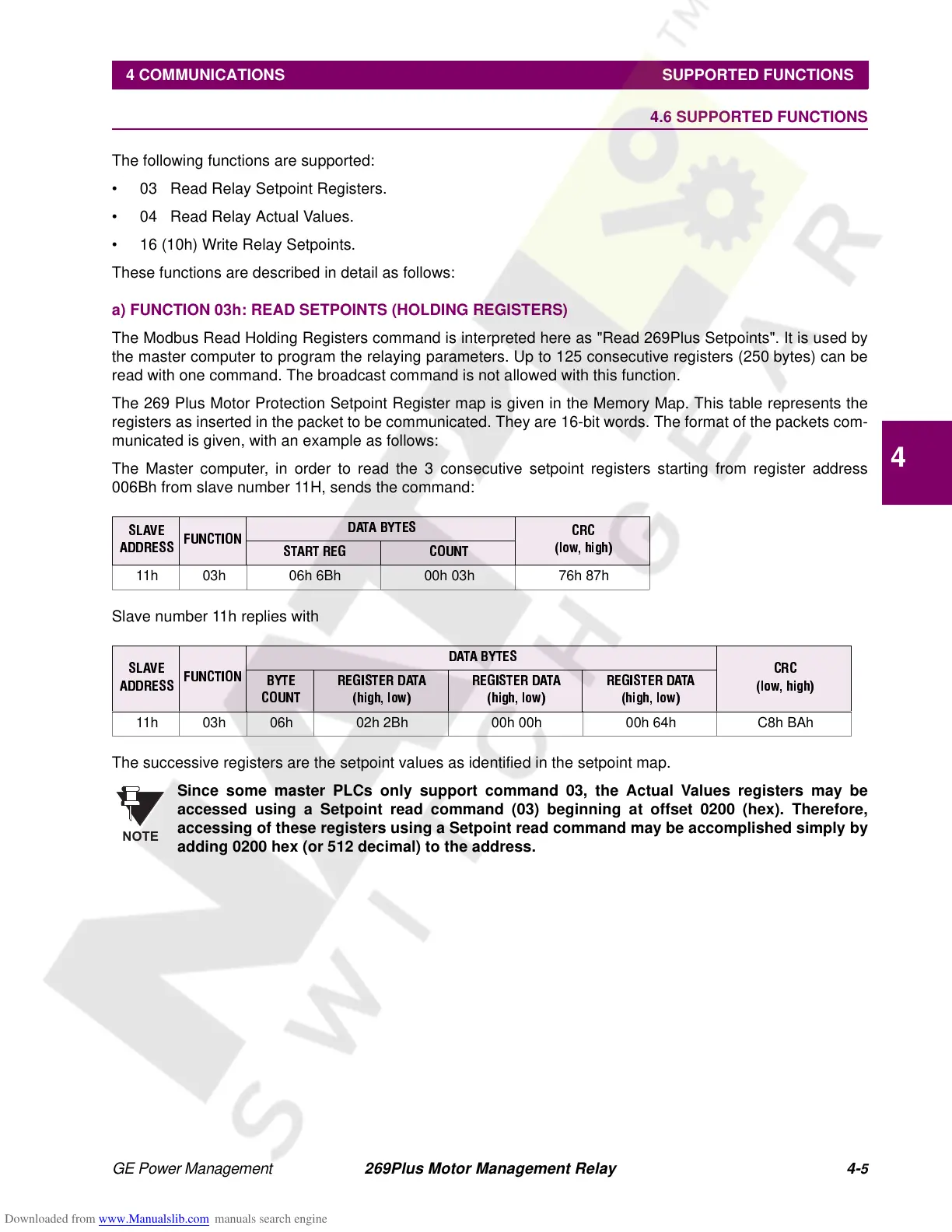
The Master computer, in order to read the 3 consecutive setpoint registers starting from register address
006Bh from slave number 11H, sends the command:
Slave number 11h replies with
The successive registers are the setpoint values as identified in the setpoint map.
Since some master PLCs only support command 03, the Actual Values registers may be
accessed using a Setpoint read command (03) beginning at offset 0200 (hex). Therefore,
accessing of these registers using a Setpoint read command may be accomplished simply by
adding 0200 hex (or 512 decimal) to the address.
SLAVE
ADDRESS
FUNCTION
DATA BYTES
CRC
(low, high)
START REG COUNT
11h 03h 06h 6Bh 00h 03h 76h 87h
SLAVE
ADDRESS
FUNCTION
DATA BYTES
CRC
(low, high)
BYTE
COUNT
REGISTER DATA
(high, low)
REGISTER DATA
(high, low)
REGISTER DATA
(high, low)
11h 03h 06h 02h 2Bh 00h 00h 00h 64h C8h BAh
NOTE