GE Power Management 269Plus Motor Management Relay 2-
1
2 INSTALLATION PHYSICAL DIMENSIONS
2
269 INSTRUCTION MANUAL 2 INSTALLATION 2.1 PHYSICAL DIMENSIONS
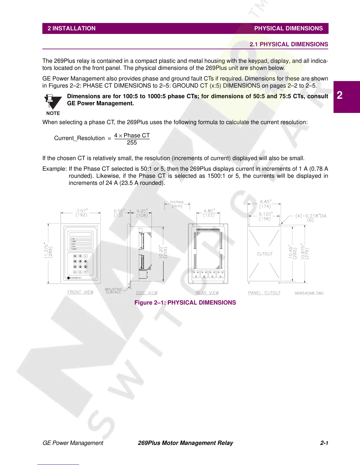
The 269Plus relay is contained in a compact plastic and metal housing with the keypad, display, and all indica-
tors located on the front panel. The physical dimensions of the 269Plus unit are shown below.
GE Power Management also provides phase and ground fault CTs if required. Dimensions for these are shown
in Figures 2–2: PHASE CT DIMENSIONS to 2–5: GROUND CT (x:5) DIMENSIONS on pages 2–2 to 2–5.
Dimensions are for 100:5 to 1000:5 phase CTs; for dimensions of 50:5 and 75:5 CTs, consult
GE Power Management.
When selecting a phase CT, the 269Plus uses the following formula to calculate the current resolution:
If the chosen CT is relatively small, the resolution (increments of current) displayed will also be small.
Example: If the Phase CT selected is 50:1 or 5, then the 269Plus displays current in increments of 1 A (0.78 A
rounded). Likewise, if the Phase CT is selected as 1500:1 or 5, the currents will be displayed in
increments of 24 A (23.5 A rounded).
Figure 2–1: PHYSICAL DIMENSIONS
NOTE
Current_Resolution
4 Phase CT×
255
------------------------------------
=