GE Power Management 269Plus Motor Management Relay 3-
15
3 SETUP AND USE ACTUAL VALUES MODE
3
To place the relay in Actual Values mode, the [ACTUAL VALUES] key must be pressed. When this is done the
following flash message appears for 2 seconds,
The display will then show the beginning of page 1:
If the relay is in Setpoints mode or Actual Values mode and no key is pressed for more than four minutes the
display will change to, (factory default settings)
which is the second line in Actual Values page 1. This default display line can be changed in Setpoints page 5.
When in this mode the [PAGE s], [PAGE t], [LINE s], and [LINE t] keys (see Section 3.2: CONTROLS
AND INDICATORS on page 3–2) can be used to examine all of the actual motor data outlined above.
a) STARTS/HOUR TIMER
An individual starts/hour timer is activated each time a motor start condition is detected and starts to time out
beginning from 60 minutes. All starts/hour timers can be viewed in Actual Values page 1, line 7. If the number
of starts/hour programmed in Setpoints page 1, line 7 is exceeded within one hour, a start/hour inhibit is initi-
ated with a lockout time equal to the smallest start/hour timer. A maximum of five starts/hour may be pro-
grammed, or the setpoint can be turned OFF.
In the case of an emergency, when the lockout time has to be bypassed and an additional start is required, the
Emergency Restart button can be pushed (Terminals #54 and 55 temporarily shorted) making the smallest
start/hour timer zero, resetting the inhibit and effectively allowing an additional start. Note that the other timers
continue to time out unaffected.
Every time the Emergency Restart button is pushed, another timer is emptied and an additional start/hour is
allowed. For example, pushing the Emergency Restart button again will empty the second timer and two more
starts/hour are allowed before another start/hour inhibit is initiated.
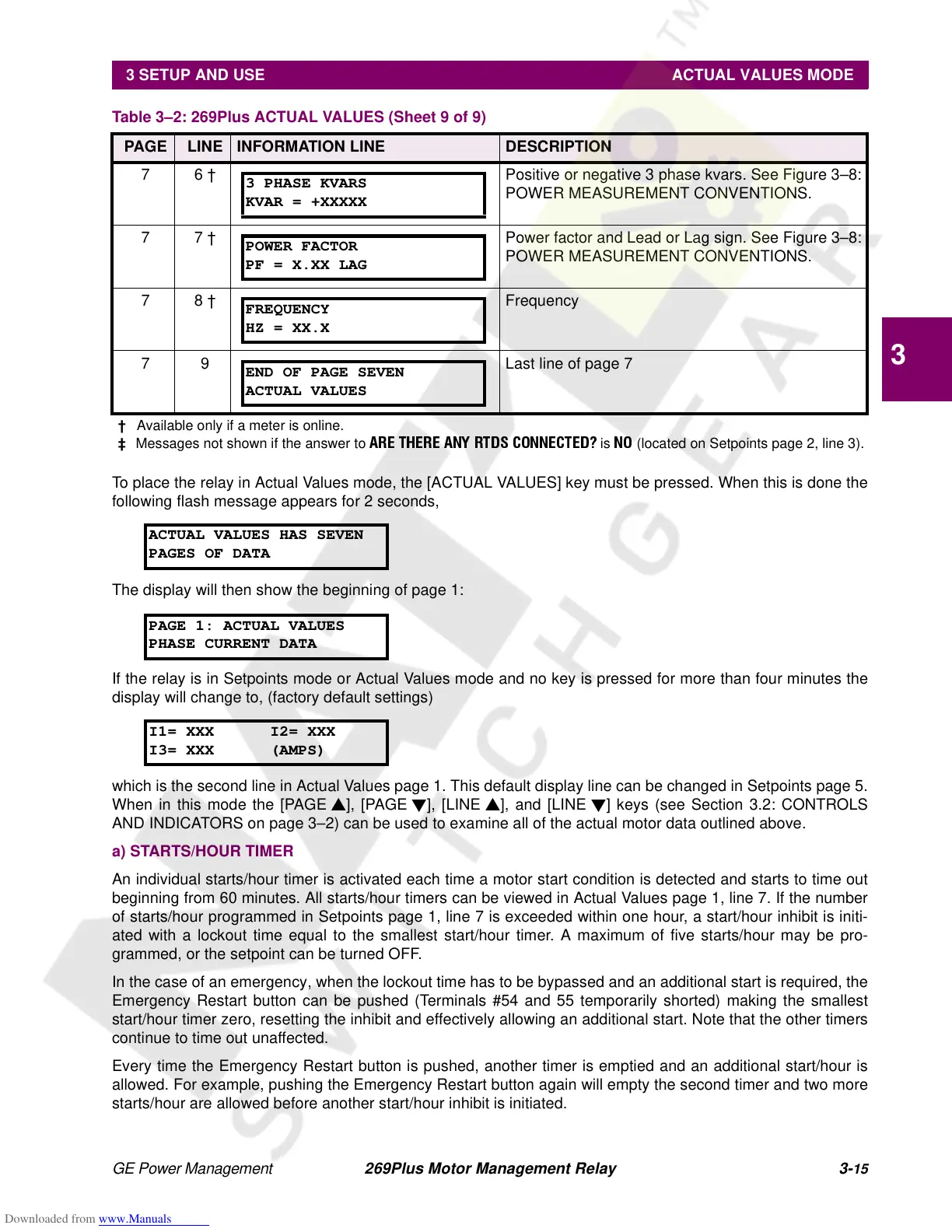
7 6 † Positive or negative 3 phase kvars. See Figure 3–8:
POWER MEASUREMENT CONVENTIONS.
7 7 † Power factor and Lead or Lag sign. See Figure 3–8:
POWER MEASUREMENT CONVENTIONS.
7 8 † Frequency
7 9 Last line of page 7
Table 3–2: 269Plus ACTUAL VALUES (Sheet 9 of 9)
PAGE LINE INFORMATION LINE DESCRIPTION
†
Available only if a meter is online.
‡
Messages not shown if the answer to
ARE THERE ANY RTDS CONNECTED?
is
NO
(located on Setpoints page 2, line 3).
3 PHASE KVARS
KVAR = +XXXXX
POWER FACTOR
PF = X.XX LAG
FREQUENCY
HZ = XX.X
END OF PAGE SEVEN
ACTUAL VALUES
ACTUAL VALUES HAS SEVEN
PAGES OF DATA
PAGE 1: ACTUAL VALUES
PHASE CURRENT DATA
I1= XXX I2= XXX
I3= XXX (AMPS)