2-
6
269Plus Motor Management Relay GE Power Management
MOUNTING 2 INSTALLATION
2
2.2 MOUNTING
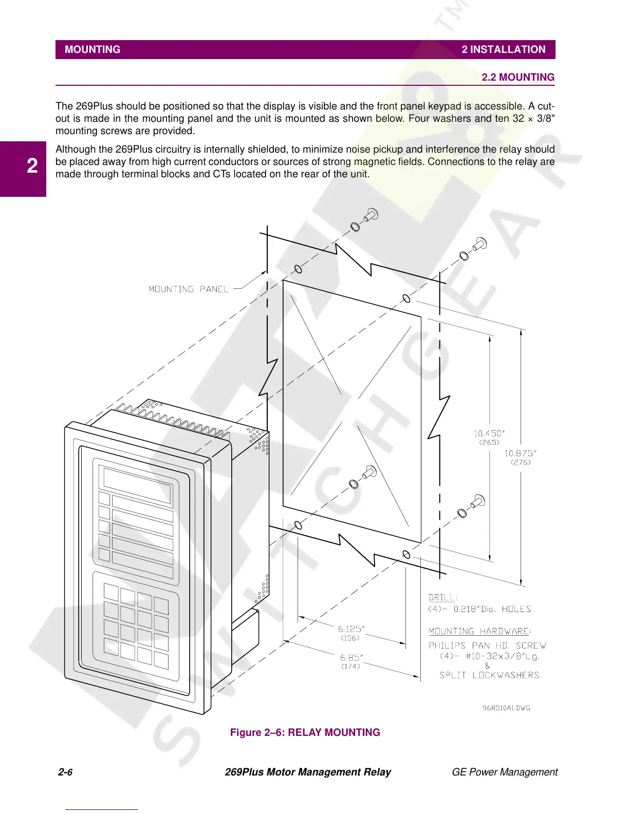
The 269Plus should be positioned so that the display is visible and the front panel keypad is accessible. A cut-
out is made in the mounting panel and the unit is mounted as shown below. Four washers and ten 32 × 3/8"
mounting screws are provided.
Although the 269Plus circuitry is internally shielded, to minimize noise pickup and interference the relay should
be placed away from high current conductors or sources of strong magnetic fields. Connections to the relay are
made through terminal blocks and CTs located on the rear of the unit.
Figure 2–6: RELAY MOUNTING