GE Power Management 269Plus Motor Management Relay C-
1
C RTD CIRCUITRY DESCRIPTION
C
APPENDIX CC RTD CIRCUITRY C.1 DESCRIPTION
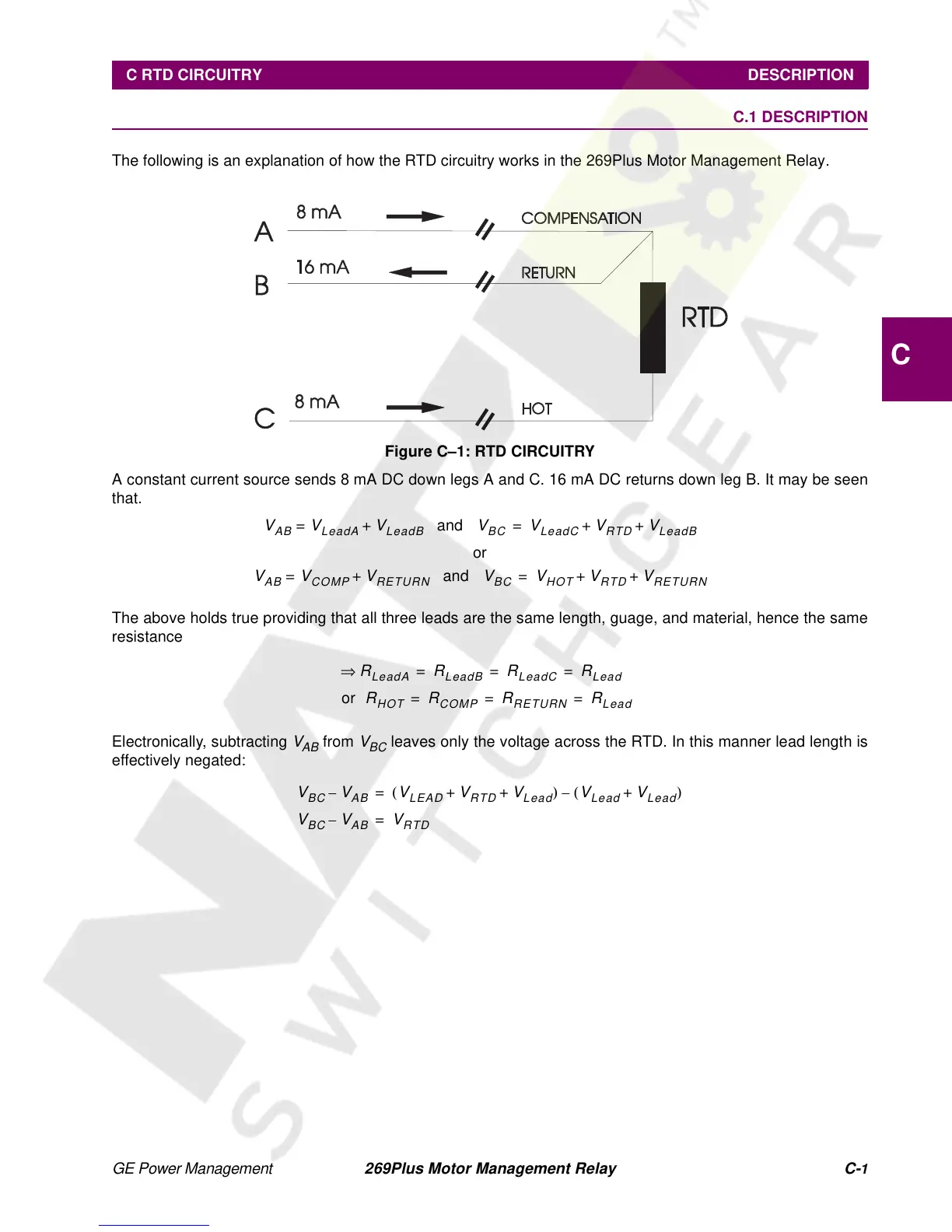
The following is an explanation of how the RTD circuitry works in the 269Plus Motor Management Relay.
Figure C–1: RTD CIRCUITRY
A constant current source sends 8 mA DC down legs A and C. 16 mA DC returns down leg B. It may be seen
that.
The above holds true providing that all three leads are the same length, guage, and material, hence the same
resistance
Electronically, subtracting
V
AB
from
V
BC
leaves only the voltage across the RTD. In this manner lead length is
effectively negated:
V
AB
V
LeadA
V
LeadB
+= and
V
BC
V
LeadC
V
RTD
V
LeadB
++=
or
V
AB
V
COMP
V
RETURN
+= and
V
BC
V
HOT
V
RTD
V
RETURN
++=
R
LeadA
⇒
R
LeadB
R
LeadC
R
Lead
===
or
R
HOT
R
COMP
R
RETURN
R
Lead
== =
V
BC
V
AB
–
V
LEAD
V
RTD
V
Lead
++()
V
Lead
V
Lead
+()–=
V
BC
V
AB
–
V
RTD
=