C-
2
269Plus Motor Management Relay GE Power Management
REDUCED WIRING RTDS C RTD CIRCUITRY
C
C.2 REDUCED WIRING RTDS
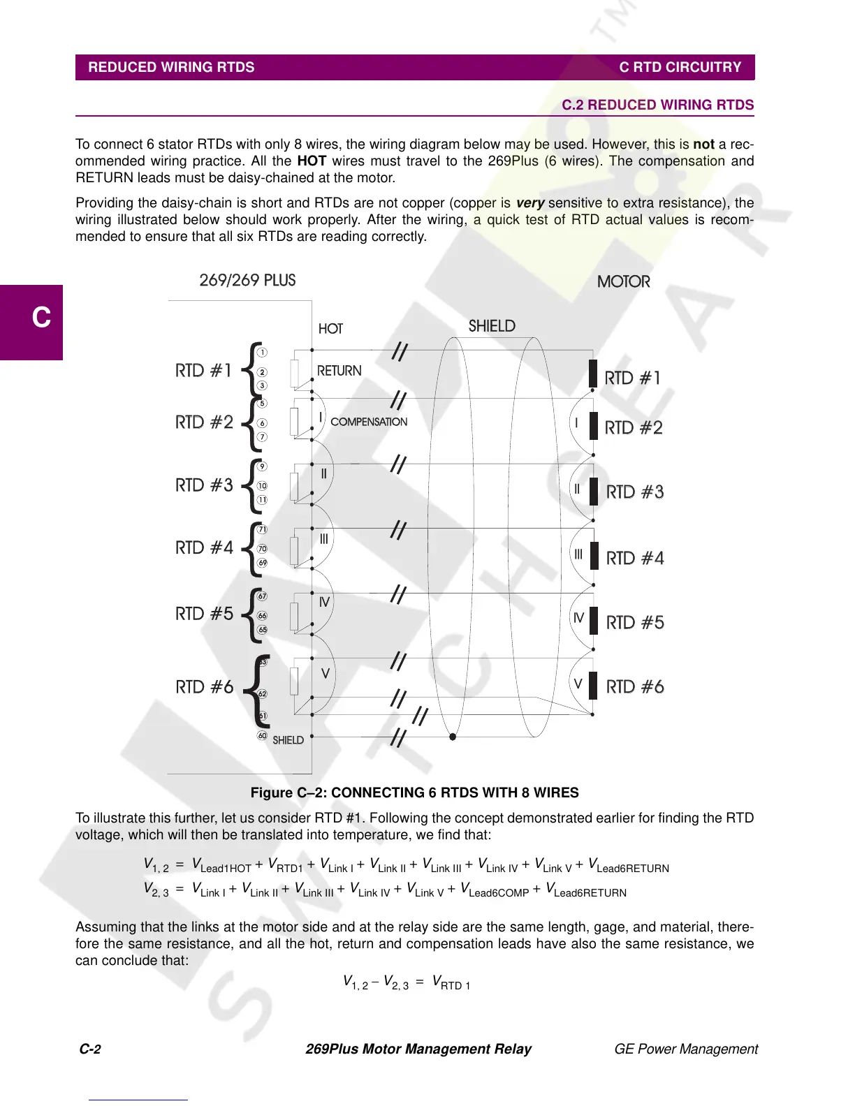
To connect 6 stator RTDs with only 8 wires, the wiring diagram below may be used. However, this is not arec-
ommended wiring practice. All the HOT wires must travel to the 269Plus (6 wires). The compensation and
RETURN leads must be daisy-chained at the motor.
Providing the daisy-chain is short and RTDs are not copper (copper is
very
sensitive to extra resistance), the
wiring illustrated below should work properly. After the wiring, a quick test of RTD actual values is recom-
mended to ensure that all six RTDs are reading correctly.
Figure C–2: CONNECTING 6 RTDS WITH 8 WIRES
To illustrate this further, let us consider RTD #1. Following the concept demonstrated earlier for finding the RTD
voltage, which will then be translated into temperature, we find that:
Assuming that the links at the motor side and at the relay side are the same length, gage, and material, there-
fore the same resistance, and all the hot, return and compensation leads have also the same resistance, we
can conclude that:
HOT
RETURN
COMPENSATION
SHIELD
1
5
9
7171
6767
6363
3
7
1111
6969
6565
6161
6060
2
2
6
1010
7070
6666
6262
269/269 PLUS269/269 PLUS
SHIELDSHIELD
=
=
=
=
=
=
=
=
=
RTD #1RTD #1
RTD #1RTD #1
RTD #2RTD #2
RTD #2RTD #2
RTD #3RTD #
RTD #3
RTD #4RTD #
RTD #4
RTD #5RTD #
RTD #5
RTD #6RTD #
RTD #6
{
{
{
{
{
{
I
II
III
IV
V
I
II
III
IV
V
MOTOOTOR
V
12
,
V
Lead1HOT
V
RTD1
V
Link I
V
Link II
V
Link III
V
Link IV
V
Link V
V
Lead6RETURN
++++ + ++=
V
23
,
V
Link I
V
Link II
V
Link III
V
Link IV
V
Link V
V
Lead6COMP
V
Lead6RETURN
++ + ++ +=
V
12
,
V
23
,
–
V
RTD 1
=