GE Power Management 269Plus Motor Management Relay 2-
7
2 INSTALLATION EXTERNAL CONNECTIONS
2
2.3 EXTERNAL CONNECTIONS
HAZARD may result if the product is not used for intended purposes. This equipment can only
be serviced by trained personnel.
Relay contacts must be considered unsafe to touch when the system in energized!
Once correct control power is applied to the 269Plus relay, a clicking sound will be heard approxi-
mately every second. This normal operation indicates that the relay is scanning through the RTDs
regardless if RTDs are in use.
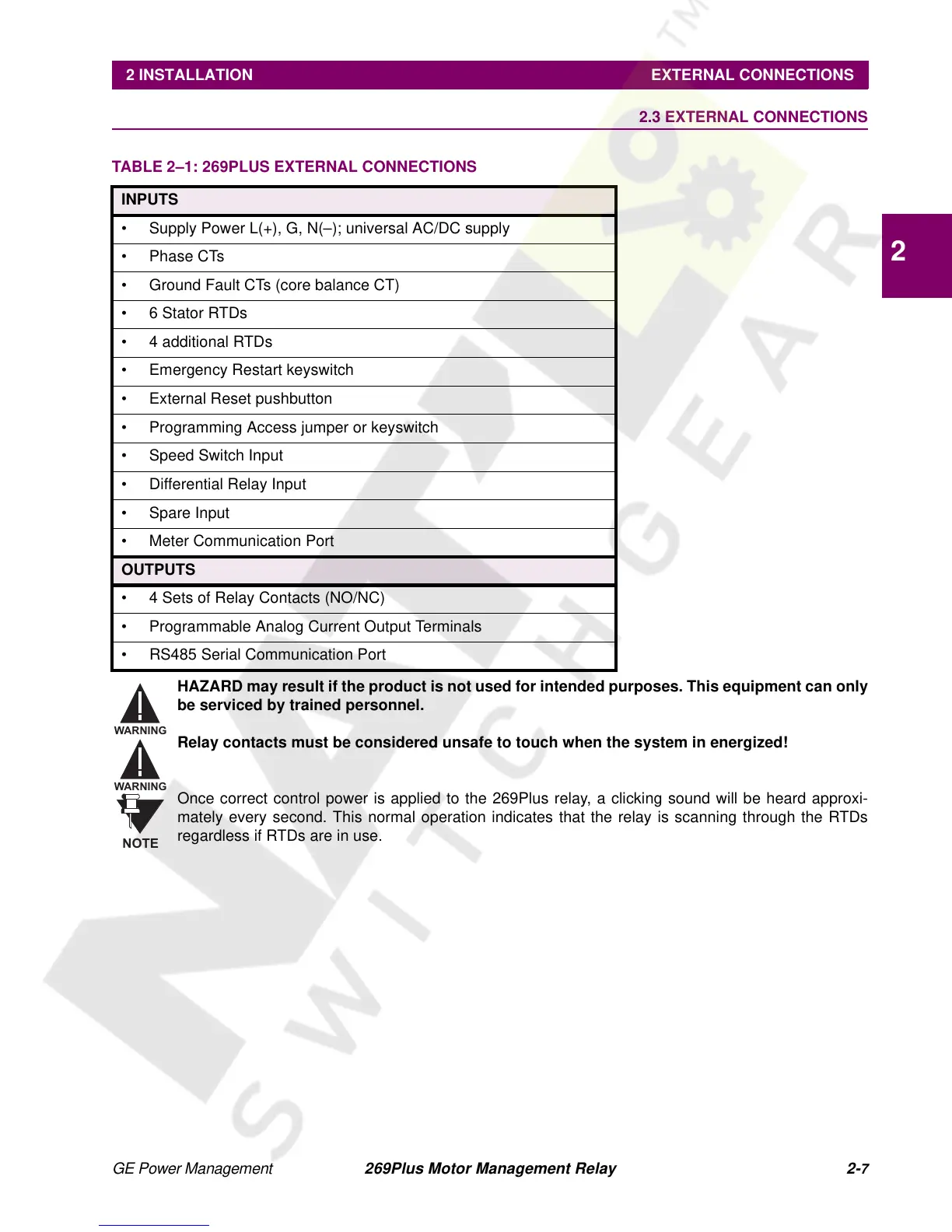
TABLE 2–1: 269PLUS EXTERNAL CONNECTIONS
INPUTS
• Supply Power L(+), G, N(–); universal AC/DC supply
•PhaseCTs
• Ground Fault CTs (core balance CT)
•6StatorRTDs
• 4 additional RTDs
• Emergency Restart keyswitch
• External Reset pushbutton
• Programming Access jumper or keyswitch
• Speed Switch Input
• Differential Relay Input
• Spare Input
• Meter Communication Port
OUTPUTS
• 4 Sets of Relay Contacts (NO/NC)
• Programmable Analog Current Output Terminals
• RS485 Serial Communication Port
WARNING
WARNING
NOTE