GE Power Management 269Plus Motor Management Relay 4-
25
4 COMMUNICATIONS FORMAT CODES
4
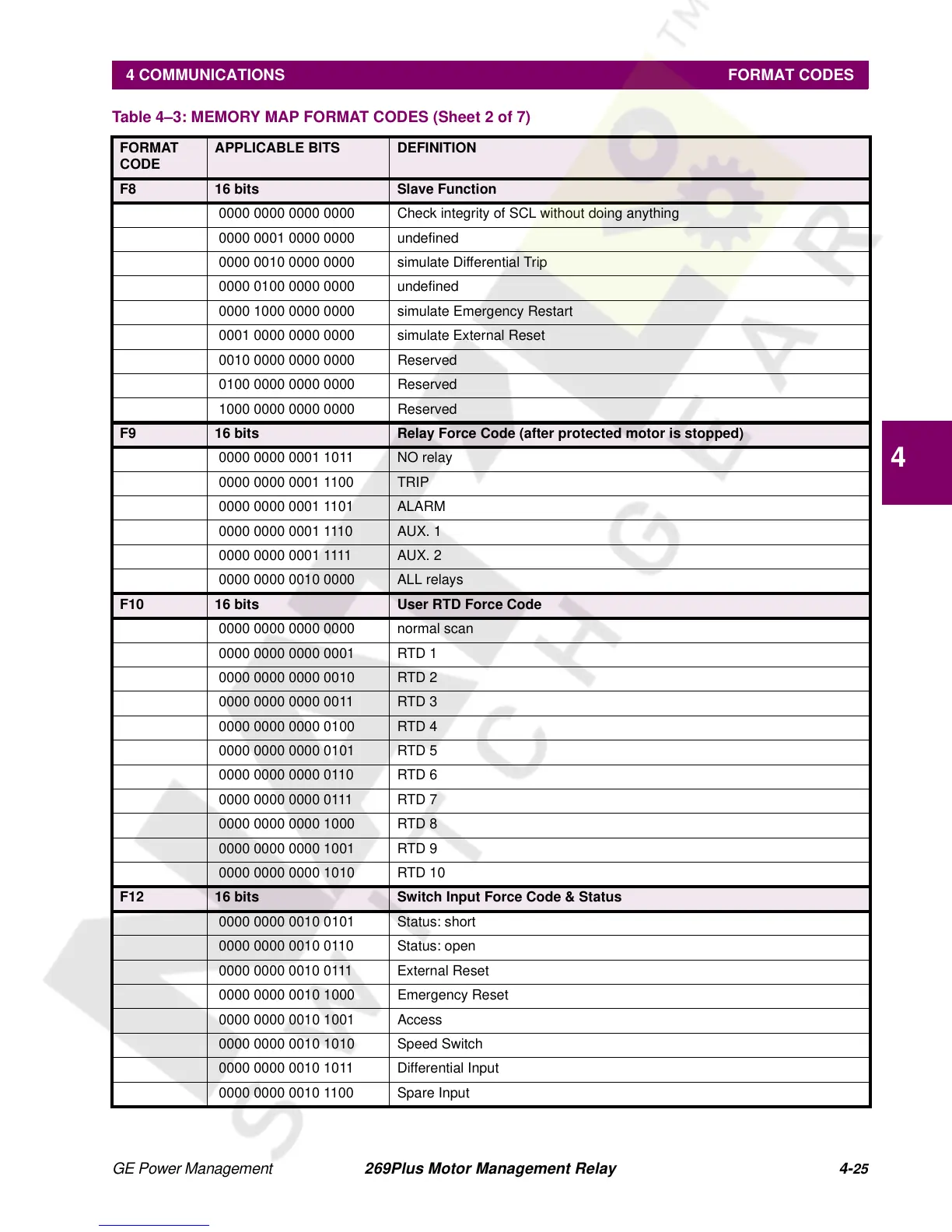
F8 16 bits Slave Function
0000 0000 0000 0000 Check integrity of SCL without doing anything
0000 0001 0000 0000 undefined
0000 0010 0000 0000 simulate Differential Trip
0000 0100 0000 0000 undefined
0000 1000 0000 0000 simulate Emergency Restart
0001 0000 0000 0000 simulate External Reset
0010 0000 0000 0000 Reserved
0100 0000 0000 0000 Reserved
1000 0000 0000 0000 Reserved
F9 16 bits Relay Force Code (after protected motor is stopped)
0000 0000 0001 1011 NO relay
0000 0000 0001 1100 TRIP
0000 0000 0001 1101 ALARM
0000 0000 0001 1110 AUX. 1
0000 0000 0001 1111 AUX. 2
0000 0000 0010 0000 ALL relays
F10 16 bits User RTD Force Code
0000 0000 0000 0000 normal scan
0000 0000 0000 0001 RTD 1
0000 0000 0000 0010 RTD 2
0000 0000 0000 0011 RTD 3
0000 0000 0000 0100 RTD 4
0000 0000 0000 0101 RTD 5
0000 0000 0000 0110 RTD 6
0000 0000 0000 0111 RTD 7
0000 0000 0000 1000 RTD 8
0000 0000 0000 1001 RTD 9
0000 0000 0000 1010 RTD 10
F12 16 bits Switch Input Force Code & Status
0000 0000 0010 0101 Status: short
0000 0000 0010 0110 Status: open
0000 0000 0010 0111 External Reset
0000 0000 0010 1000 Emergency Reset
0000 0000 0010 1001 Access
0000 0000 0010 1010 Speed Switch
0000 0000 0010 1011 Differential Input
0000 0000 0010 1100 Spare Input
Table 4–3: MEMORY MAP FORMAT CODES (Sheet 2 of 7)
FORMAT
CODE
APPLICABLE BITS DEFINITION