GE Power Management 269Plus Motor Management Relay 3-
67
3 SETUP AND USE METER OPTION
3
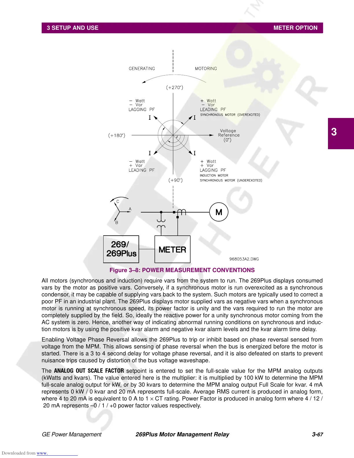
Figure 3–8: POWER MEASUREMENT CONVENTIONS
All motors (synchronous and induction) require vars from the system to run. The 269Plus displays consumed
vars by the motor as positive vars. Conversely, if a synchronous motor is run overexcited as a synchronous
condensor, it may be capable of supplying vars back to the system. Such motors are typically used to correct a
poor PF in an industrial plant. The 269Plus displays motor supplied vars as negative vars when a synchronous
motor is running at synchronous speed, its power factor is unity and the vars required to run the motor are
completely supplied by the field. So, ideally the reactive power for a unity synchronous motor coming from the
AC system is zero. Hence, another way of indicating abnormal running conditions on synchronous and induc-
tion motors is by using the positive kvar alarm and negative kvar alarm levels and the kvar alarm time delay.
Enabling Voltage Phase Reversal allows the 269Plus to trip or inhibit based on phase reversal sensed from
voltage from the MPM. This allows sensing of phase reversal when the bus is energized before the motor is
started. There is a 3 to 4 second delay for voltage phase reversal, and it is also defeated on starts to prevent
nuisance trips caused by distortion of the bus voltage waveshape.
The
ANALOG OUT SCALE FACTOR
setpoint is entered to set the full-scale value for the MPM analog outputs
(kWatts and kvars). The value entered here is the multiplier: it is multiplied by 100 kW to determine the MPM
full-scale analog output for kW, or by 30 kvars to determine the MPM analog output Full Scale for kvar. 4 mA
represents 0 kW / 0 kvar and 20 mA represents full-scale. Average RMS current is produced in analog form,
where 4 to 20 mA is equivalent to 0 A to 1 × CT rating. Power Factor is produced in analog form where 4 / 12 /
20 mA represents –0 / 1 / +0 power factor values respectively.