7-
2
269Plus Motor Management Relay GE Power Management
USING FLC THERMAL CAPACITY REDUCTION SETPOINT 7 APPLICATION EXAMPLES
7
From the formula:
we have:
Therefore, the Thermal Capacity Reduction = 30%
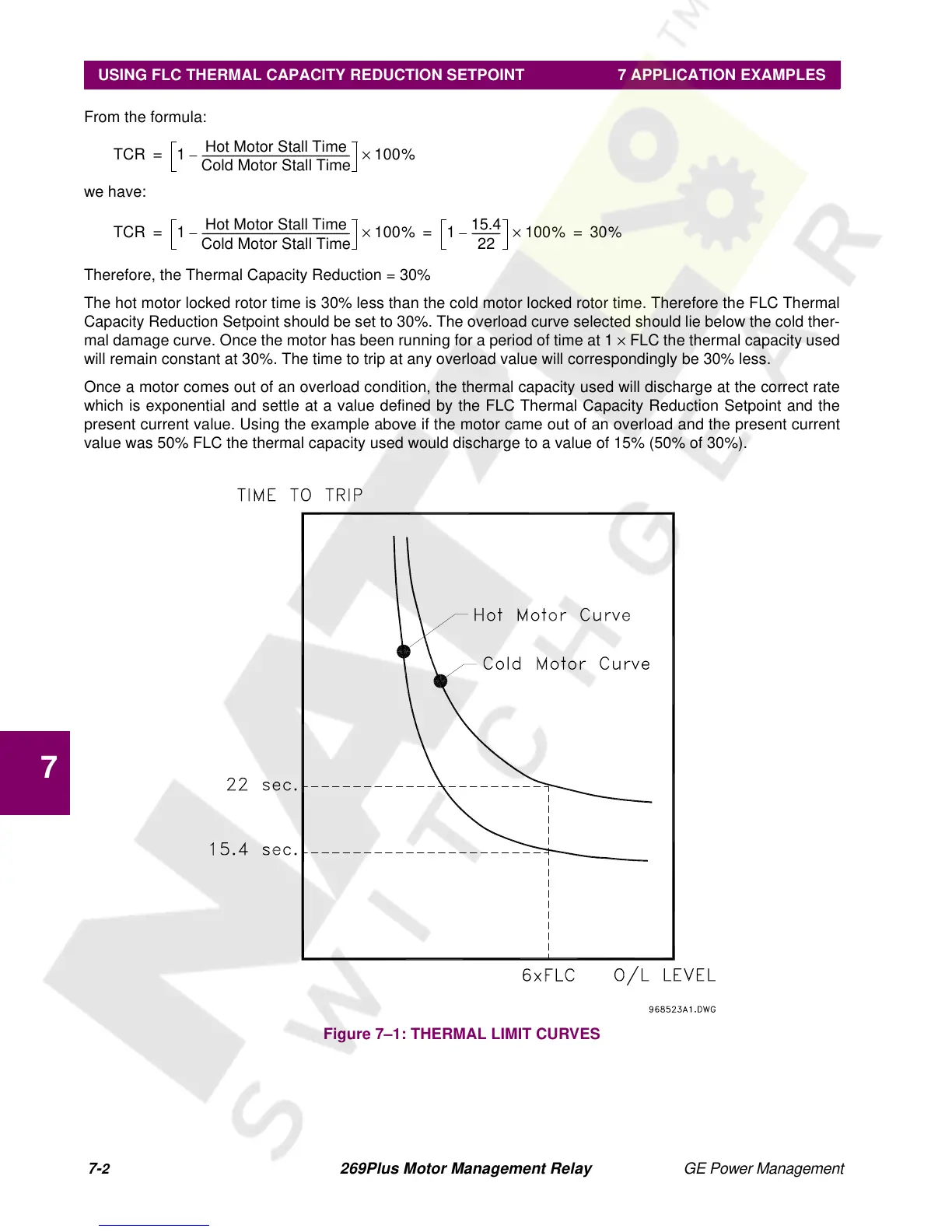
The hot motor locked rotor time is 30% less than the cold motor locked rotor time. Therefore the FLC Thermal
Capacity Reduction Setpoint should be set to 30%. The overload curve selected should lie below the cold ther-
mal damage curve. Once the motor has been running for a period of time at 1 × FLC the thermal capacity used
will remain constant at 30%. The time to trip at any overload value will correspondingly be 30% less.
Once a motor comes out of an overload condition, the thermal capacity used will discharge at the correct rate
which is exponential and settle at a value defined by the FLC Thermal Capacity Reduction Setpoint and the
present current value. Using the example above if the motor came out of an overload and the present current
value was 50% FLC the thermal capacity used would discharge to a value of 15% (50% of 30%).
Figure 7–1: THERMAL LIMIT CURVES
TCR 1
Hot Motor Stall Time
Cold Motor Stall Time
---------------------------------------------------------
– 100%×=
TCR 1
Hot Motor Stall Time
Cold Motor Stall Time
---------------------------------------------------------– 100%× 1
15.4
22
-----------– 100%× 30%===