GE Power Management 269Plus Motor Management Relay 2-
9
2 INSTALLATION EXTERNAL CONNECTIONS
2
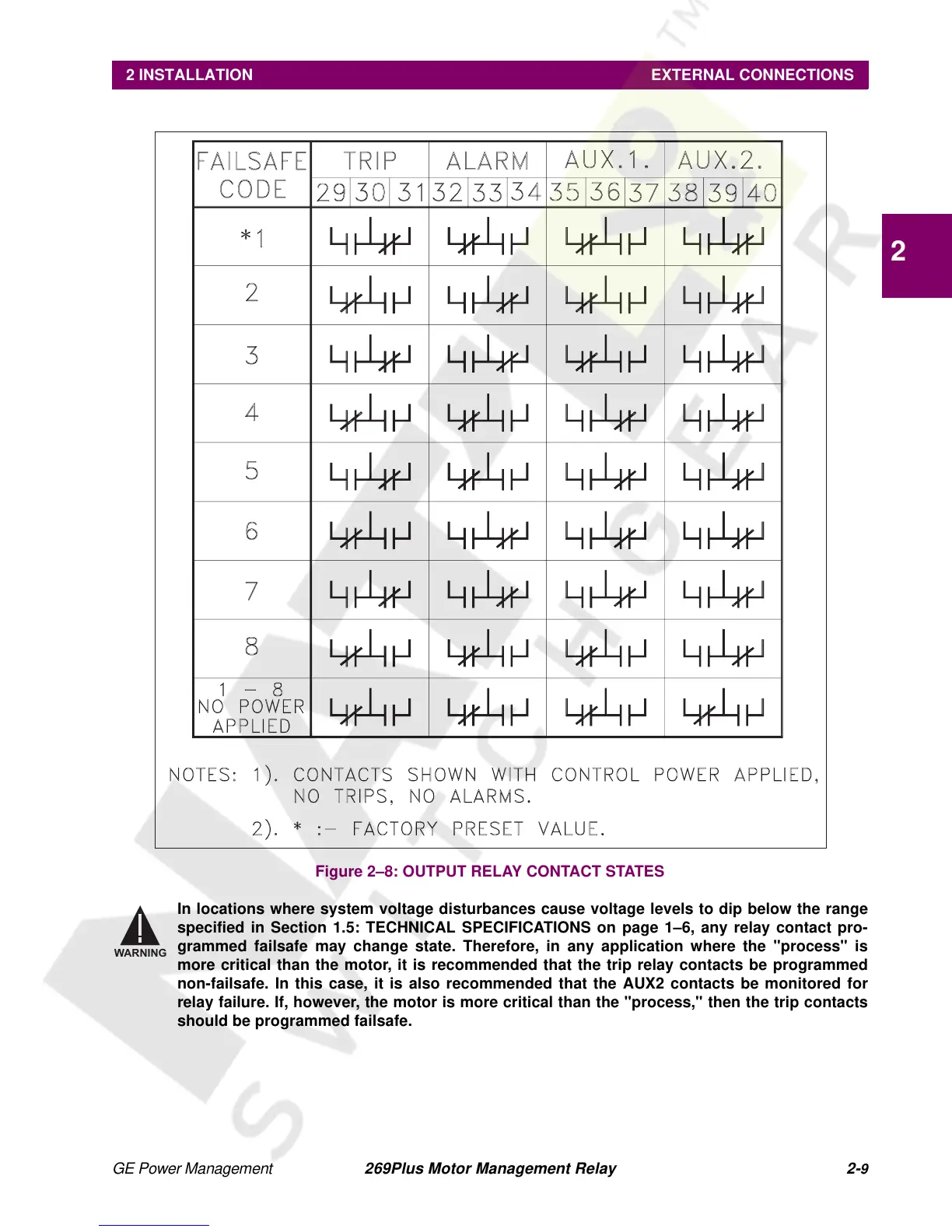
Figure 2–8: OUTPUT RELAY CONTACT STATES
In locations where system voltage disturbances cause voltage levels to dip below the range
specified in Section 1.5: TECHNICAL SPECIFICATIONS on page 1–6, any relay contact pro-
grammed failsafe may change state. Therefore, in any application where the "process" is
more critical than the motor, it is recommended that the trip relay contacts be programmed
non-failsafe. In this case, it is also recommended that the AUX2 contacts be monitored for
relay failure. If, however, the motor is more critical than the "process," then the trip contacts
should be programmed failsafe.
WARNING