GE Power Management 269Plus Motor Management Relay 3-
29
3 SETUP AND USE SETPOINTS MODE
3
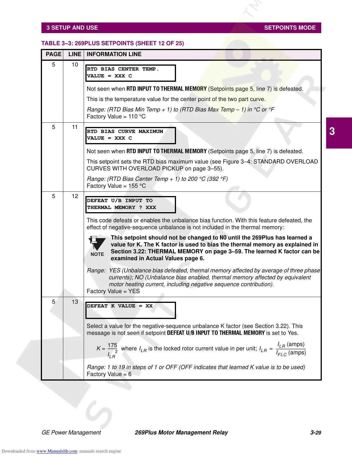
510
Not seen when
RTD INPUT TO THERMAL MEMORY
(Setpoints page 5, line 7) is defeated.
This is the temperature value for the center point of the two part curve.
Range: (RTD Bias Min Temp + 1) to (RTD Bias Max Temp – 1) in °C or °F
Factory Value = 110 °C
511
Not seen when
RTD INPUT TO THERMAL MEMORY
(Setpoints page 5, line 7) is defeated.
This setpoint sets the RTD bias maximum value (see Figure 3–4: STANDARD OVERLOAD
CURVES WITH OVERLOAD PICKUP on page 3–55).
Range: (RTD Bias Center Temp + 1) to 200 °C (392 °F)
Factory Value = 155 °C
512
This code defeats or enables the unbalance bias function. With this feature defeated, the
effect of negative-sequence unbalance is not included in the thermal memory:
This setpoint should not be changed to
NO
until the 269Plus has learned a
value for K. The K factor is used to bias the thermal memory as explained in
Section 3.22: THERMAL MEMORY on page 3–59. The learned K factor can be
examined in Actual Values page 6.
Range: YES (Unbalance bias defeated, thermal memory affected by average of three phase
currents); NO (Unbalance bias enabled, thermal memory affected by equivalent
motor heating current, including negative sequence contribution).
Factory Value = YES
513
Select a value for the negative-sequence unbalance K factor (see Section 3.22). This
message is not seen if setpoint
DEFEAT U/B INPUT TO THERMAL MEMORY
is set to Yes.
Range: 1 to 19 in steps of 1 or OFF (OFF indicates that learned K value is to be used)
Factory Value = 6
TABLE 3–3: 269PLUS SETPOINTS (SHEET 12 OF 25)
PAGE LINE INFORMATION LINE
RTD BIAS CENTER TEMP.
VALUE = XXX C
RTD BIAS CURVE MAXIMUM
VALUE = XXX C
DEFEAT U/B INPUT TO
THERMAL MEMORY ? XXX
NOTE
DEFEAT K VALUE = XX
K
175
I
LR
2
----------
where=
I
LR
is the locked rotor current value in per unit;
I
LR
I
LR
(amps)
I
FLC
(amps)
-------------------------------=