DIRECTION 5750007-1EN, REV. 1 LOGIQ E10 BASIC SERVICE MANUAL
8 - 94 Section 8-7 - Replacing Top Console Parts
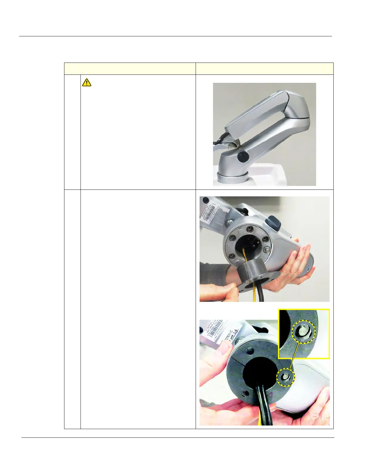
Monitor Arm assembly installation
Table 8-108 Monitor Arm assembly installation
Steps Corresponding Graphic
1.
WARNINGWARNING
WHEN INSTALLING THE MONITOR
ARM, KEEP THE ARM LOCKED, AS
SHOWN TO ENSURE THE MONITOR
ARM ASSEMBLY IS IN THE LOCKED
POSITION UNTILL THE ARM AND
MONITOR ARE INSTALLED. THE
SPRINGS TO SUPPORT THE MONITOR
CAN CAUSE THE ARM TO SPRING
OPEN CAUSING SEVERE PERSONAL
INJURY AND PROPERTY DAMAGE.
2.
Make sure the Bushing is installed and
positioned in the orientation shown. The
larger hole in the Bushing is to
accommodate the pin.