DIRECTION 5750007-1EN, REV. 1 LOGIQ E10 BASIC SERVICE MANUAL
8 - 142 Section 8-7 - Replacing Top Console Parts
Trackball Assembly removal
Table 8-162 Trackball Assembly removal
Steps Corresponding Graphic
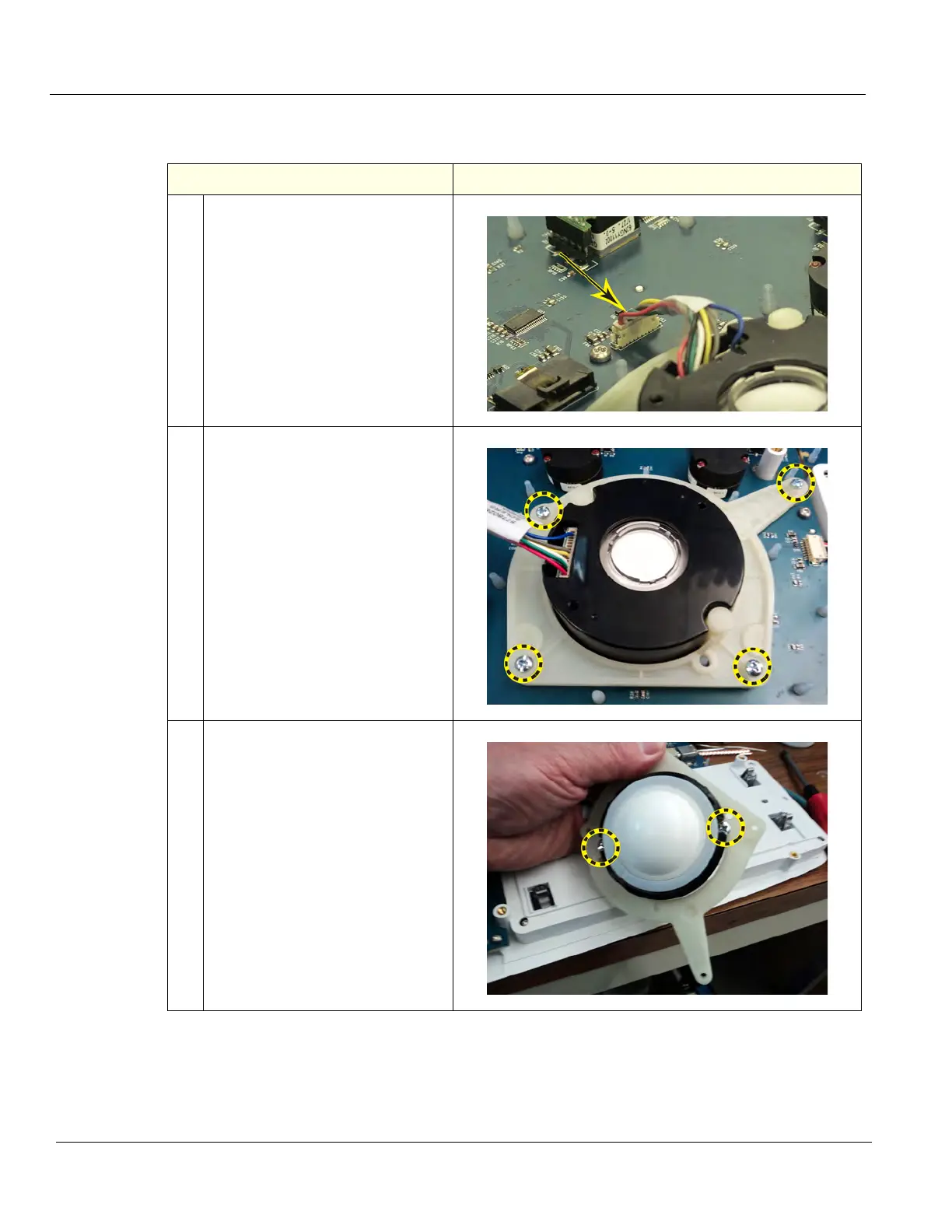
1. Disconnect the signal cable
connector from the Lower Switch
and Encoder Board.
Grasp the connector on the large,
flat sides and pull straight away
from the board.
The Trackball includes the
Trackball Cable.
The Customer Removable
Trackball can be cleaned from the
top.
2.
Remove the four screws securing
the Trackball Mounting Bracket to
the Bezel, using a #1 Phillips
Screwdriver.
3. Remove the two screws securing
the Trackball the Trackball
Mounting Bracket.
Note the orientation of the Cable in
the Bracket.