DIRECTION 5750007-1EN, REV. 1 LOGIQ E10 BASIC SERVICE MANUAL
Chapter 8 Replacement Procedures 8 - 143
Trackball Assembly Installation
Calibration and adjustments
Verification
Perform the following steps to verify that the product is functioning as intended after this replacement:
1.) Verify that all screws removed earlier have been installed.
2.) Connect cables and Probes removed earlier.
3.) Power up the system to verify that it operates as intended.
4.) Verify that the Trackball operates as intended.
Functional Checks
Perform the following functional checks to confirm the system is operational before returning the system
to the customer.
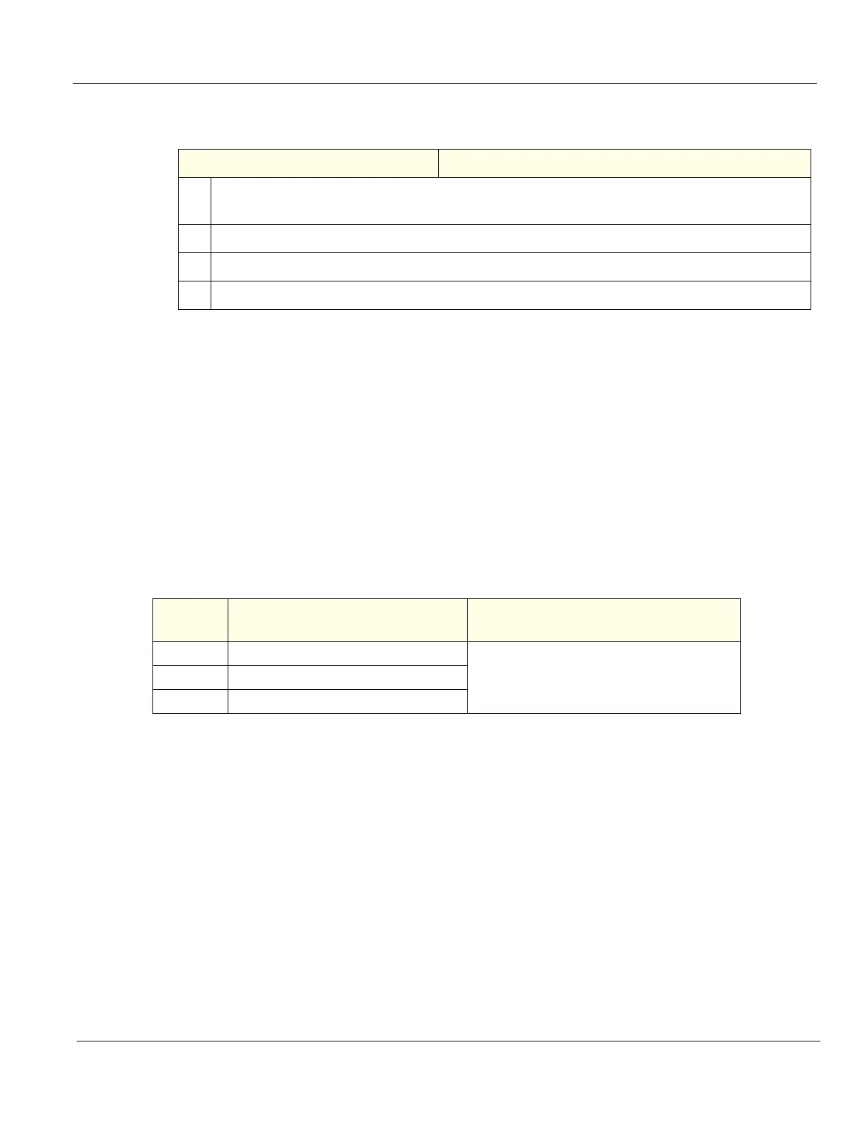
Table 8-163 Trackball Assembly Installation
Steps Corresponding Graphic
1. Re-install the screws to secure the Trackball the Trackball Mounting Bracket.
Remember the orientation of the Cable in the Bracket.
2.
Re-install the screws to secure the Trackball Mounting Bracket to the Bezel.
3. Connect the signal cable connector to the Lower Switch and Encoder Board.
4. Re-install Lower and Upper OP and all Covers removed.
Table 8-164 Trackball Assembly replacement Functional Checks
See:
Section Functional Check Debrief Script
4-2-3 Power ON/Boot Up
LOGIQ E10 Basic Service Manual, Direction
5750007-1EN, Rev. 1. Equipment passed all
required checks and is ready for use.
4-2-7 B-Mode Checks
4-2-4 Power SHUT DOWN