DIRECTION 5750007-1EN, REV. 1 LOGIQ E10 BASIC SERVICE MANUAL
Chapter 8 Replacement Procedures 8 - 153
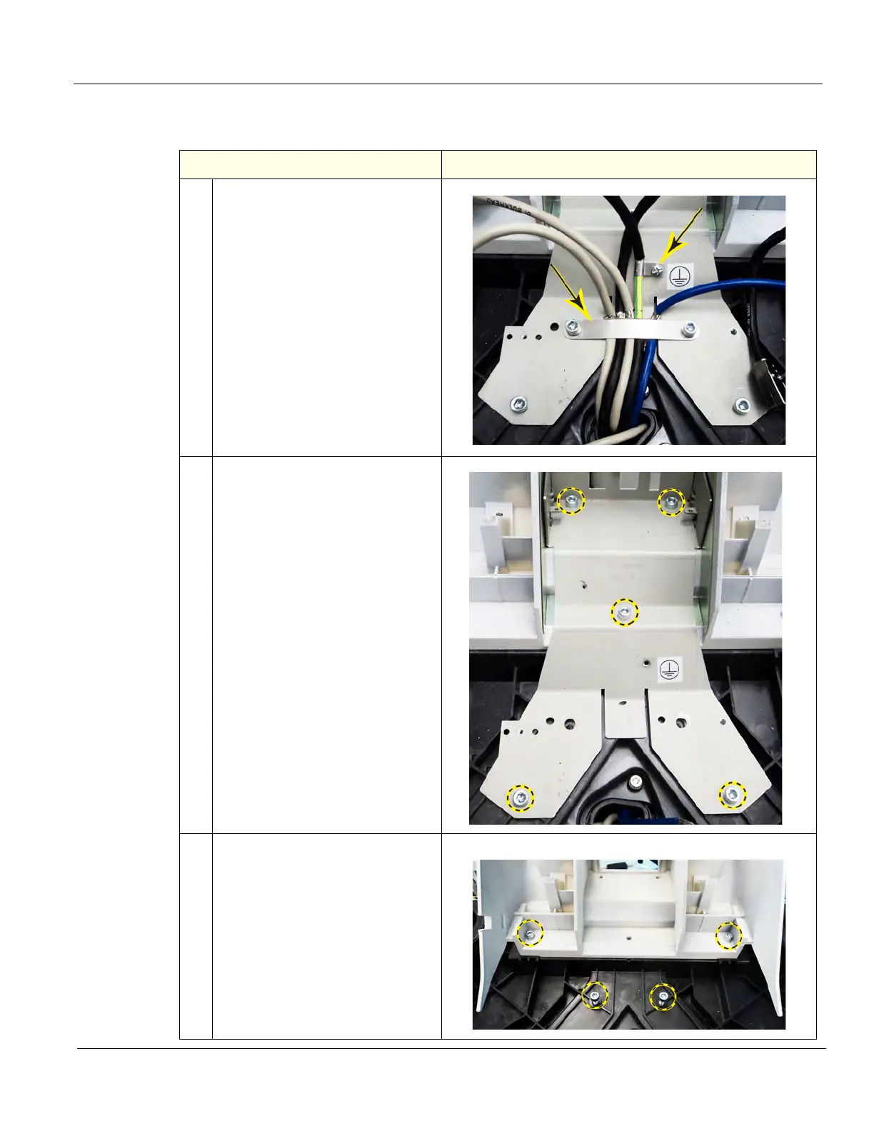
Upper OP Frame removal
Table 8-177 Upper OP Frame removal
Steps Corresponding Graphic
1. Remove the Grounding Strap
Clamp, using a 5 mm hex wrench
and the P-clamp screw and lock
washer, using a #1 Phillips
screwdriver.
2. Remove the five fixing screws
securing the Bulkhead Plate, using
a 5 mm hex wrench.
Note that the upper two screws are
shorter.
• uppers 20 mm long
• middle 45 mm long
• lowers 25 mm long
Remove the Bulkhead Plate and the
Bulkhead Bracket Housing (behind
the plate).
3. Re-install two screws loosely
(bottom) to hold the Lower UI
Frame when the Upper Frame is
removed.
NOTE: Support the Upper UI Frame
when the remaining screws are
removed.
Remove the two remaining screws
securing the Upper UI Frame to the
Lower UI Frame, using a 5 mm hex
wrench.