EasyManuals Logo

GE LOGIQ E10 Service Manual

GE LOGIQ E10
778 pages
To Next Page IconTo Next Page
To Previous Page IconTo Previous Page
Page #433 background imageLoading...
Page #433 background image
DIRECTION 5750007-1EN, REV. 1 LOGIQ E10 BASIC SERVICE MANUAL
Chapter 8 Replacement Procedures 8 - 187
8-8-2 XY Brake Motor replacement (cont’d)
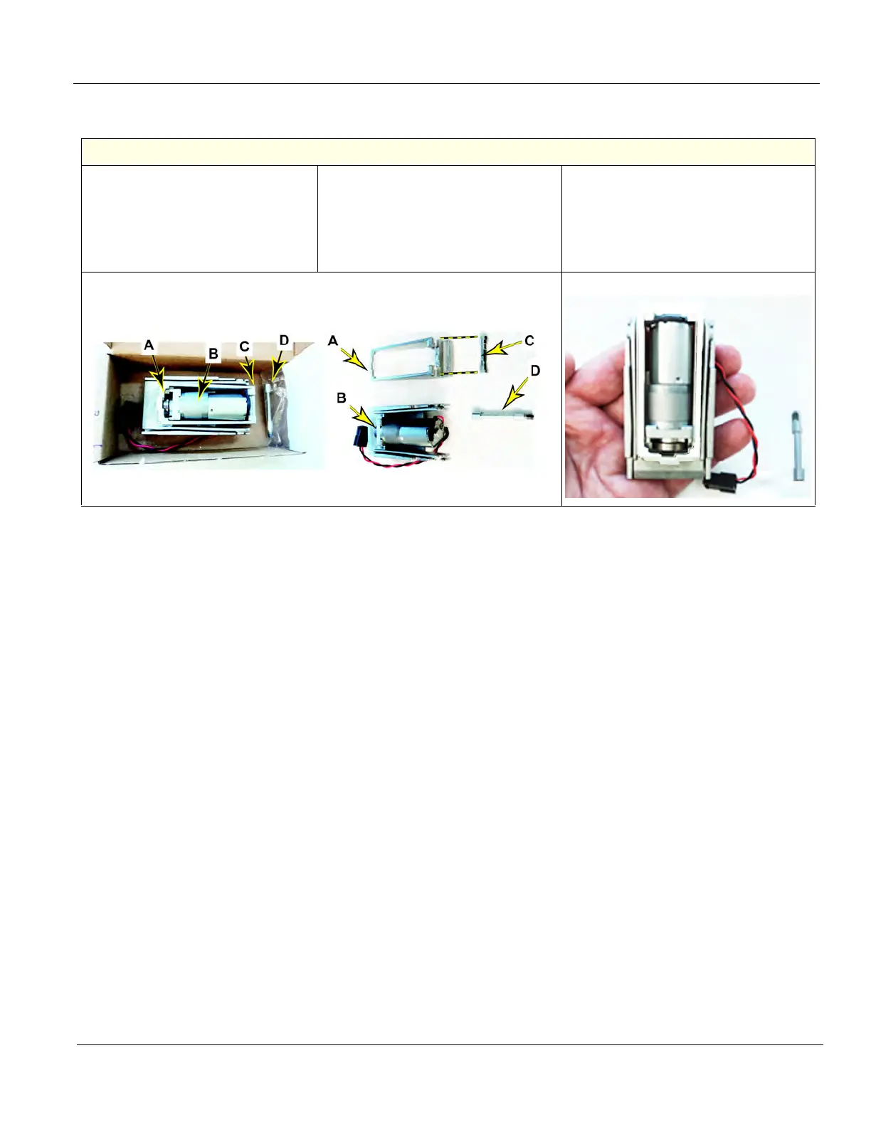
How XY Brake Motor Assembly is Packaged
P/N 5737394 is packaged in four pieces:
A. XY Hinge
B. Motor Assembly
C. Tension Adjustment Screw
D. Roller (threaded)
(packaging material, not shown)
The XY Hinge (A) rests on the Motor
Assembly (B) and it MUST be in that
position and the Tension Adjustment
Screw MUST be installed when the
Assembly is installed.
MAKE SURE to have the XY Hinge resting
on the Motor Assembly and the Tension
Adjustment Screw installed during the
Assembly installation.

Table of Contents

Other manuals for GE LOGIQ E10

Questions and Answers:

Question and Answer IconNeed help?

Do you have a question about the GE LOGIQ E10 and is the answer not in the manual?

GE LOGIQ E10 Specifications

General IconGeneral
TouchscreenYes
3D/4D ImagingYes
ApplicationsVascular, Cardiac, Musculoskeletal, OB/GYN
Image StorageUSB, Network
ConnectivityDICOM, Ethernet, Wireless

Related product manuals