DIRECTION 5750007-1EN, REV. 1 LOGIQ E10 BASIC SERVICE MANUAL
8 - 190 Section 8-8 - Replacing XYZ Parts
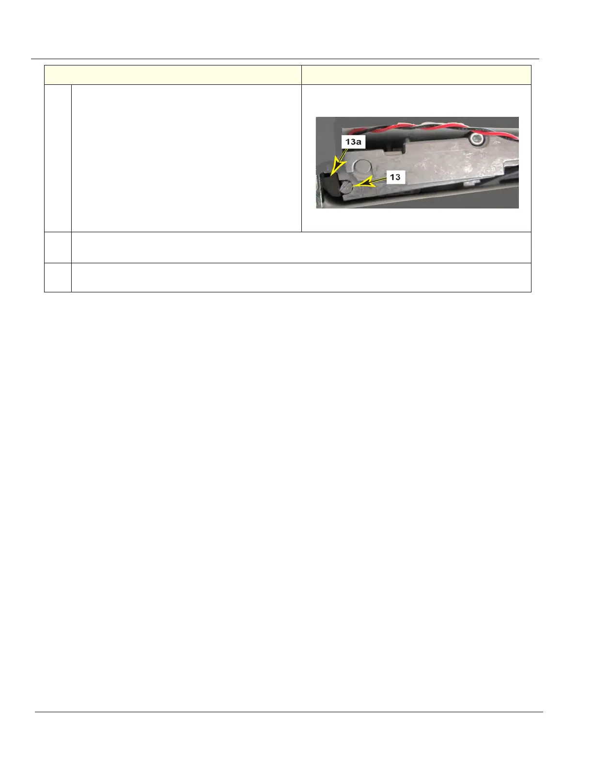
13.
This step is intended for adjusting the motor tension,
to make sure the lock motor operates properly.
Push and hold the XY unlock push-button on the
front of the controls console (see Step 3 for
reference), to keep the lock motor assembly
released.
At the same time, with a flat blade screwdriver, turn
the tension adjustment screw (13) clockwise, so that
the flat side of the screw faces away from the brake
shoe (13a).
NOTE: See Note in Step 8 for proper adjustment of
the tension screw, if needed.
14.
Push the XY unlock push-button and confirm that the replaced lock motor(s) expands and releases.
Release the XY unlock push-button and confirm the lock motor(s) stay locked.
15. Replace the plastic flogleg cover(s) and secure each with the same TORX retaining screws used in Step 6.
Torque to 1 Nm.
Steps
Corresponding Graphic