DIRECTION 5750007-1EN, REV. 1 LOGIQ E10 BASIC SERVICE MANUAL
Chapter 8 Replacement Procedures 8 - 211
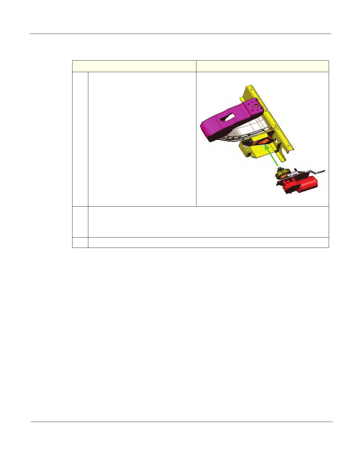
Drive Gear Assembly installation
Table 8-236 Drive Gear Assembly installation
Step Corresponding Graphic
1. NOTE: When attaching the replacement
assembly, you need to carefully work the
new assembly into place, wiggling the
motor assembly and the Top Console until
the shaft slides into the bearing.
Insert the Drive Gear assembly in the front
top, checking that the lever and motor
body are not wedged on the Frame. Install
it from the top and at an angle, ensuring
that the release lever goes through the
release lever opening in the back of the
LOGIQ E10.
You may need to either operate the
Z-Mech release lever when positioning, or
move the Top Console slightly up or down
to engage the teeth on the wheel with the
teeth on the gear.
Install the four fixing screws with washers.
(M6 x 16, torque: 9.5 Nm {7.0 lbf-ft}.)
Drive Gear Assembly placement
2. Connect the motor cable from the XYZ Control Box and the Volume Navigation ground lead, if
present.
Power up the Ultrasound System and verify that the XYZ function as intended.
Power down the Ultrasound System.
3. Re-install all Covers removed.