DIRECTION 5750007-1EN, REV. 1 LOGIQ E10 BASIC SERVICE MANUAL
8 - 210 Section 8-8 - Replacing XYZ Parts
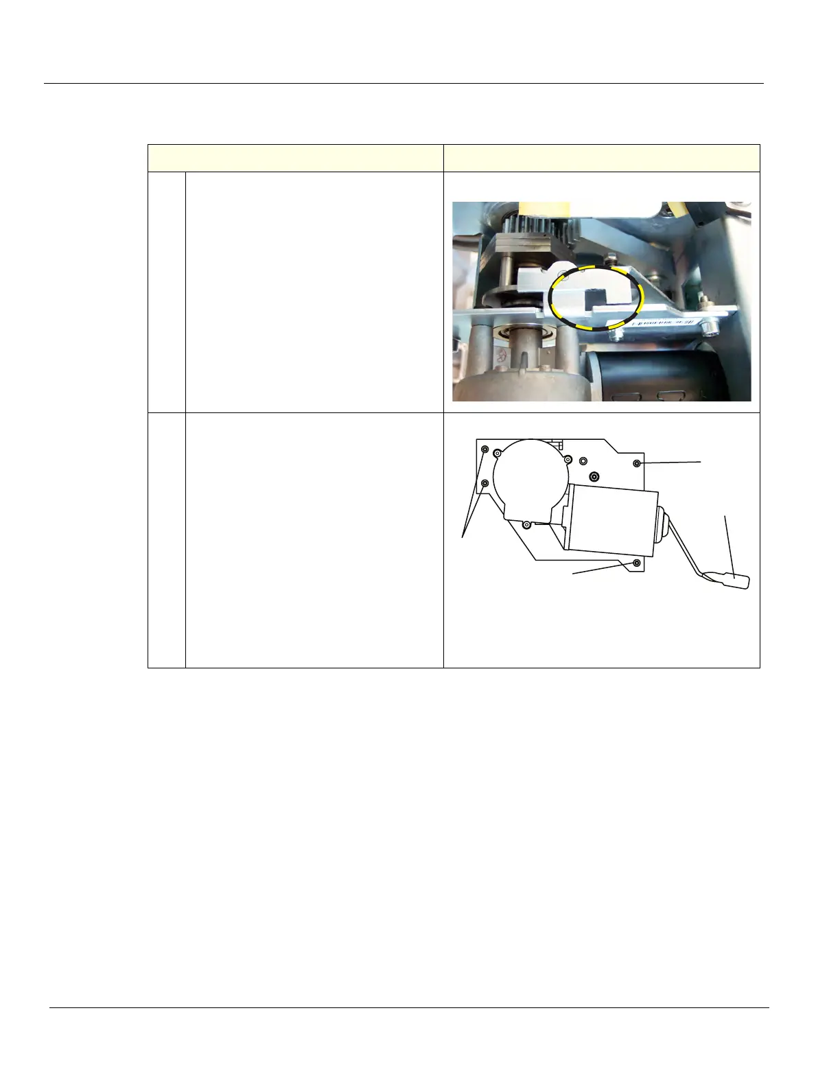
Drive Gear Assembly removal
Table 8-235 Drive Gear Assembly removal
Step Corresponding Graphic
1. The Drive Gear can be removed by
guiding the release lever as the drive
motor is being removed from the
Ultrasound System.
Slot on Drive Gear
2. The Drive Gear Assembly is a part of the
Z-Mechanism. To remove the Drive Gear
Assembly.
Place a piece of paper on top of the Card
Rack to prevent any debris which may
have developed from Drive Gear
Assembly.
Disconnect the motor cable from the XYZ
Control Box and the Volume Navigation
ground lead, if present.
Unscrew and remove the four fixing
screws (1). Use a 5 mm L-Allen wrench
with a Ball Head to take off the whole
assembly (four bolts).
Push the release lever (2) to its maximum.
2
1
1
1