DIRECTION 5750007-1EN, REV. 1 LOGIQ E10 BASIC SERVICE MANUAL
8 - 214 Section 8-8 - Replacing XYZ Parts
8-8-6 XYZ Control Assembly replacement (cont’d)
XYZ Control Assembly removal
NOTE: There is a USB cable connected to the XYZ Controller, from J11 of the ECB. The cable must
also be removed from the USB port labeled USB Interface of the controller.
Figure 8-7 XYZ Control Assembly
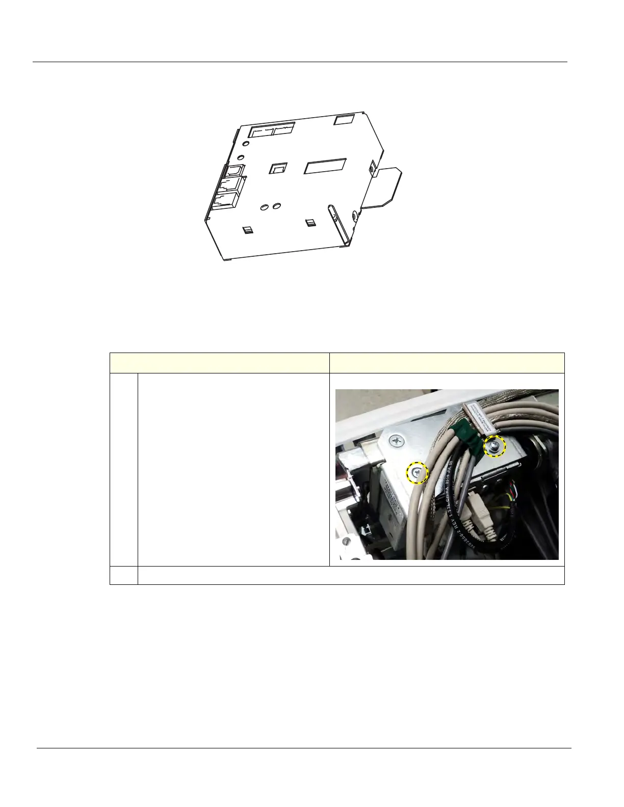
Table 8-240 XYZ Control Assembly removal
Step Corresponding Graphic
1. Take note of how the cables are
positioned in the grounding clamp, the
cables MUST BE returned in the same
manner.
Disconnect the cables to the XYZ Control
Assembly.
Remove the two screws securing the XYZ
Control and cable clamp.
2. Pull the top of the XYZ Control Assembly forwards, away and up from the bracket.