EasyManuals Logo

GE LOGIQ E10 Service Manual

GE LOGIQ E10
778 pages
To Next Page IconTo Next Page
To Previous Page IconTo Previous Page
Page #486 background imageLoading...
Page #486 background image
DIRECTION 5750007-1EN, REV. 1 LOGIQ E10 BASIC SERVICE MANUAL
8 - 240 Section 8-10 - Casters and Brakes replacement
Pedal Mechanism removal
Table 8-264 Pedal Mechanism removal
Steps Corresponding Graphic
1. Power down the LOGIQ E10 and lock the Rear Casters.
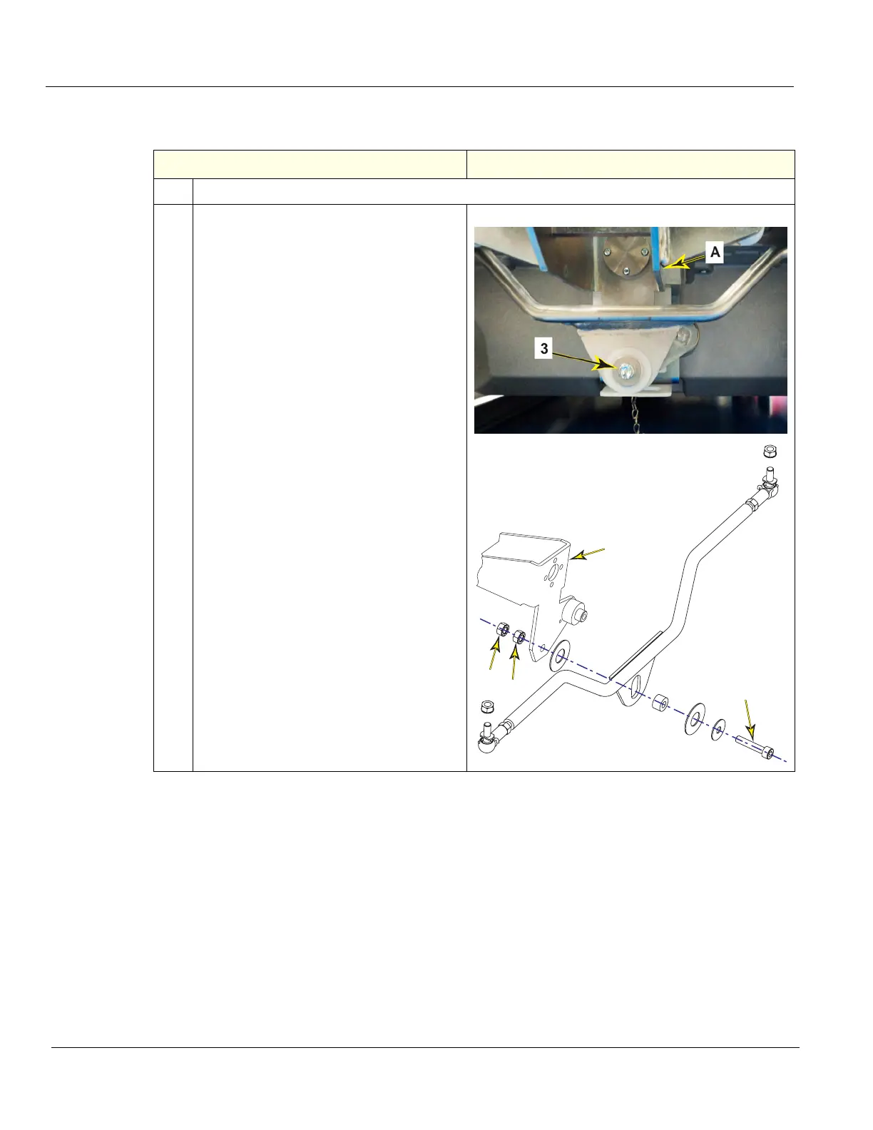
2.
Using a 10 mm open-end wrench, secure
flange nut (1) and loosen flange nut (2 -
“locking” nut). remove “locking” nut (2).
Remove pivot screw (3 - below Pedal
Mechanism Assembly A), while holding
flange nut (1), capture the hardware as it is
removed.
Note the sequence of all the hardware
removed, it MUST BE re-installed in the
same manner.
1
2
3
A

Table of Contents

Other manuals for GE LOGIQ E10

Questions and Answers:

Question and Answer IconNeed help?

Do you have a question about the GE LOGIQ E10 and is the answer not in the manual?

GE LOGIQ E10 Specifications

General IconGeneral
TouchscreenYes
3D/4D ImagingYes
ApplicationsVascular, Cardiac, Musculoskeletal, OB/GYN
Image StorageUSB, Network
ConnectivityDICOM, Ethernet, Wireless

Related product manuals