DIRECTION 5750007-1EN, REV. 1 LOGIQ E10 BASIC SERVICE MANUAL
Chapter 8 Replacement Procedures 8 - 245
8-10-6 Pedal Mechanism Cam FRU replacement (cont’d)
NOTE: It is not necessary to remove the Pedal Mechanism to replace the Pedal Mechanism Cam. To
simplify the installation of the Cam, it is important to understand the location and how the Cam
is positioned in the Pedal Mechanism.
Table 8-268 Cam to Pedal Mechanism replacement
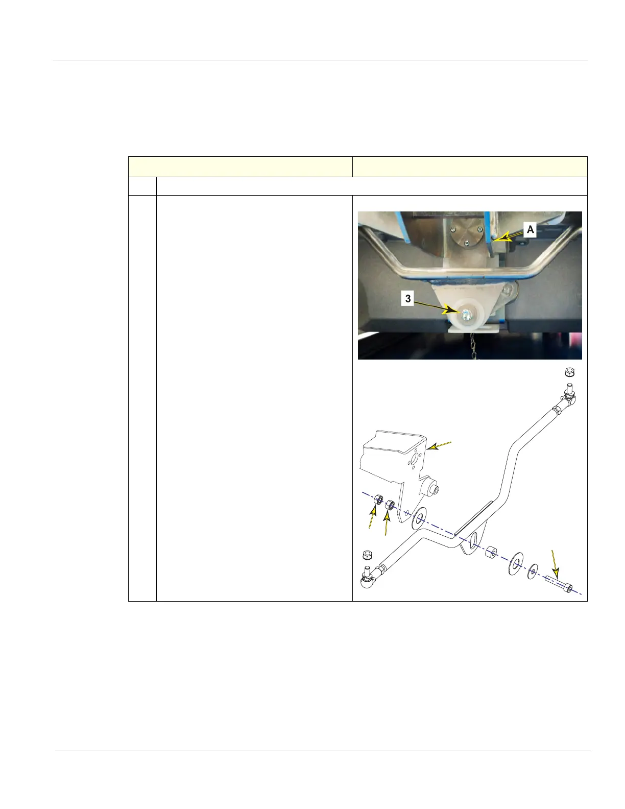
Steps Corresponding Graphic
1. Power down the LOGIQ E10 and lock the Rear Casters.
2.
Using a 10 mm open-end wrench, secure
flange nut (1) and loosen flange nut (2 -
“locking” nut). remove “locking” nut (2).
Remove pivot screw (3 - below Pedal
Mechanism Assembly A), while holding
flange nut (1), capture the hardware as it is
removed.
Note the sequence of all the hardware
removed, it MUST BE re-installed in the
same manner.
1
2
3
A