DIRECTION 5750007-1EN, REV. 1 LOGIQ E10 BASIC SERVICE MANUAL
Chapter 8 Replacement Procedures 8 - 319
6.
Remove the two flange nuts securing the
4D Motor Controller Cover and slide the
Cover out.
7.
Remove the two screws securing the 4D
Motor Controller, using a #1 Phillips
screwdriver.
DO NOT discard the two screws.
The 4D Motor Controller connects to the
Backplane on the right end.
With your thumb and index finger, gently
grasp the Board at the right top and bottom,
and gently remove the Board from the
Backplane.
NOTE: If the screwlocks stay on the
Backplane, transfer them to the
replacement Backplane.
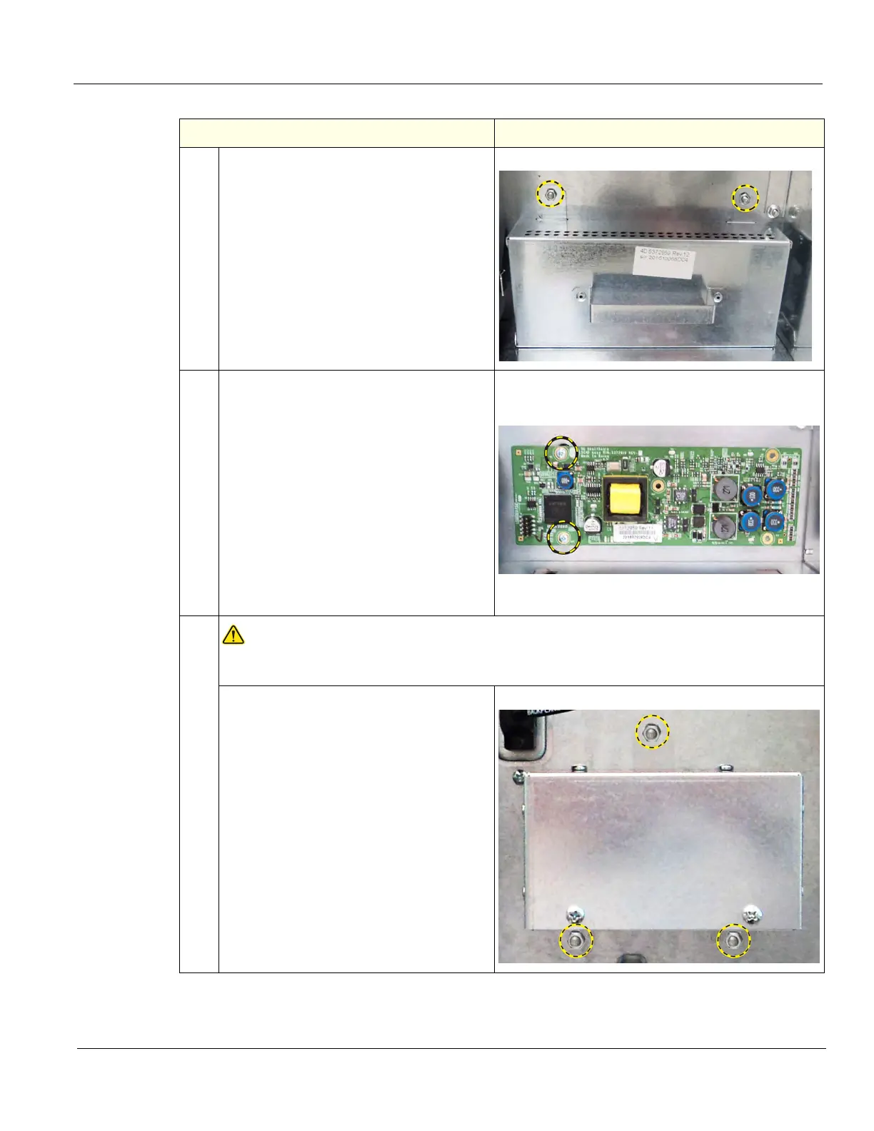
8.
DANGER
DANGEROUS VOLTAGES, CAPABLE OF CAUSING DEATH, ARE PRESENT IN THIS
EQUIPMENT. DO NOT REMOVE THE CAPACITOR PACK COVER.
Remove the three flange nuts securing the
Shear Wave Capacitor Pack.
The Capacitor Pack will support itself on
the options bracket.
With both hands, slide the Capacitor Pack
from the Backplane.
Table 8-334 Connector Panel replacement
Steps Corresponding Graphic