EasyManuals Logo

GE LOGIQ E10 Service Manual

GE LOGIQ E10
778 pages
To Next Page IconTo Next Page
To Previous Page IconTo Previous Page
Page #567 background imageLoading...
Page #567 background image
DIRECTION 5750007-1EN, REV. 1 LOGIQ E10 BASIC SERVICE MANUAL
Chapter 8 Replacement Procedures 8 - 321
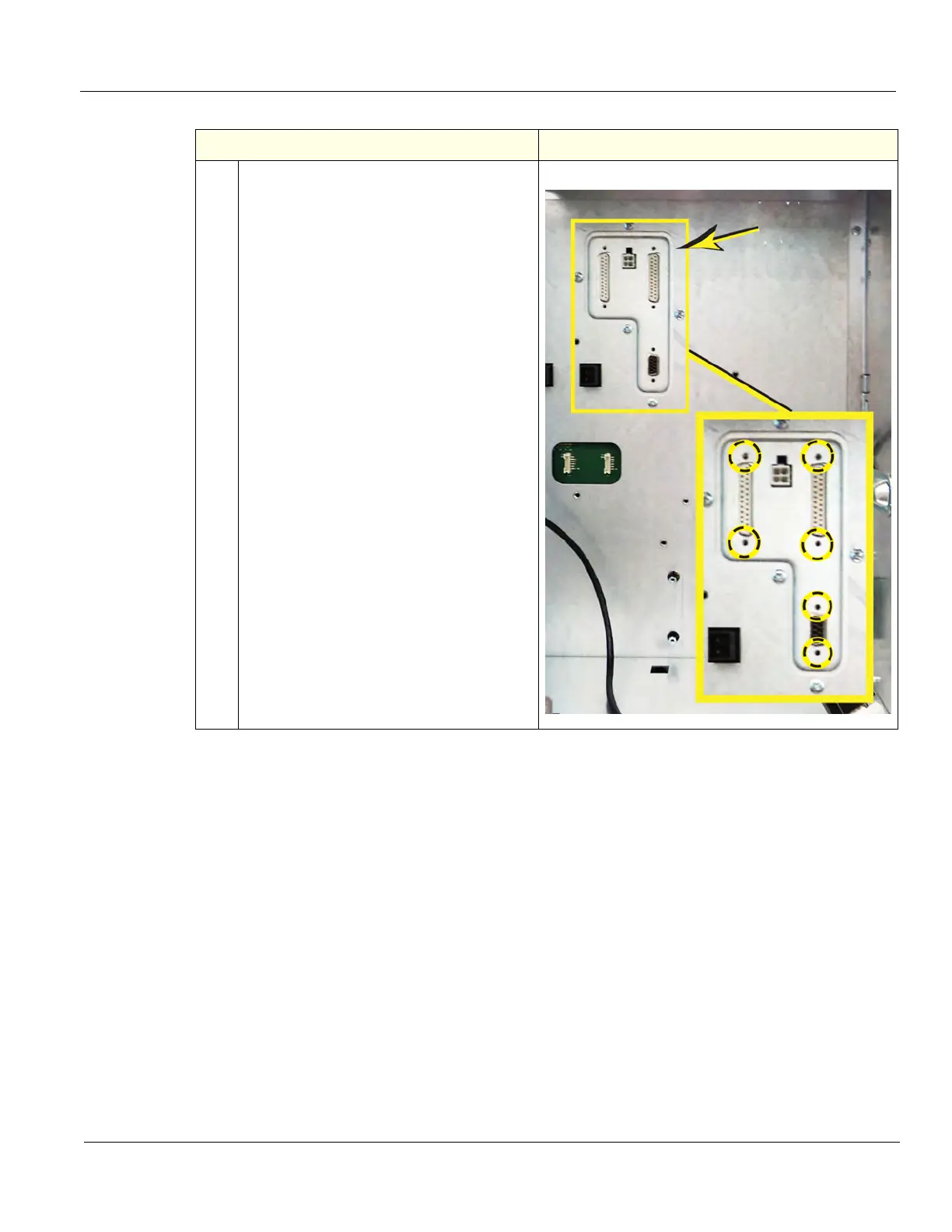
10.
Remove the four hex screwlocks (.312
inches long, on the right) and two locking
posts (on the left) attached to the
Connector Panel, using a 3/16 hex driver.
DO NOT discard the hex screwlocks or the
locking posts.
Table 8-334 Connector Panel replacement
Steps Corresponding Graphic

Table of Contents

Other manuals for GE LOGIQ E10

Questions and Answers:

Question and Answer IconNeed help?

Do you have a question about the GE LOGIQ E10 and is the answer not in the manual?

GE LOGIQ E10 Specifications

General IconGeneral
TouchscreenYes
3D/4D ImagingYes
ApplicationsVascular, Cardiac, Musculoskeletal, OB/GYN
Image StorageUSB, Network
ConnectivityDICOM, Ethernet, Wireless

Related product manuals