DIRECTION 5750007-1EN, REV. 1 LOGIQ E10 BASIC SERVICE MANUAL
8 - 410 Section 8-16 - Options replacement
4D Option removal
For location of the Option in the LOGIQ E10, see: Table 8-401 "LOGIQ E10 Option Location" on page
8-408.
4D Option installation
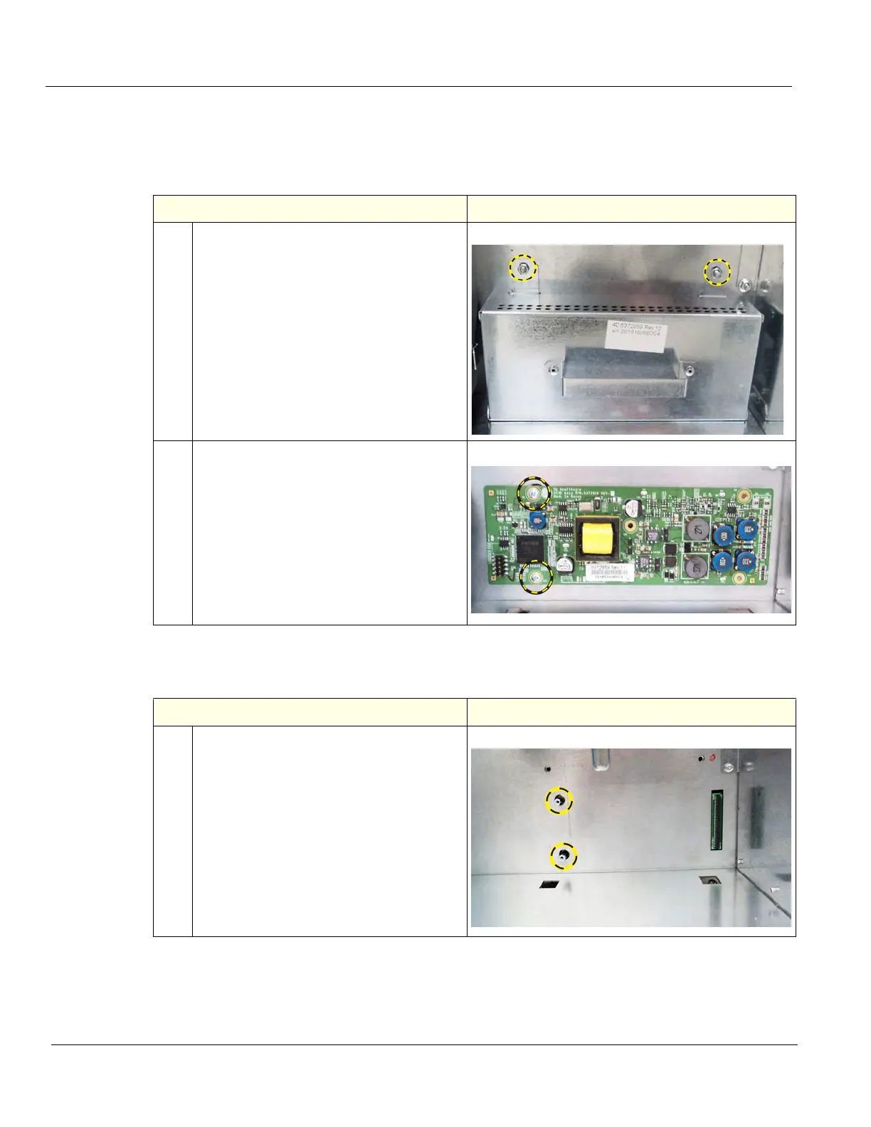
Table 8-404 4D Option removal
Steps Corresponding Graphic
1.
Remove the two flange nuts securing the
4D Motor Controller Cover, using a 7 mm
driver and slide the Cover out.
2.
Remove the two screws securing the 4D
Motor Controller, using a #1 Phillips
screwdriver.
The 4D Motor Controller connects to the
Backplane on the right end.
With your thumb and index finger, gently
grasp the Board at the right top and bottom,
and gently remove the Board from the
Backplane.
Table 8-405 4D Option installation
Steps Corresponding Graphic
1.
The 4D Option attaches to the Backplane
with the screws removed and to the
screwlocks.