Adjustable foot
The adjustable foot is placed in the front right corner of the rocker base when viewed
from the front. It is used to distribute weight evenly over the four rocker feet.
Use the supplied adjustable foot wrench to adjust the foot.
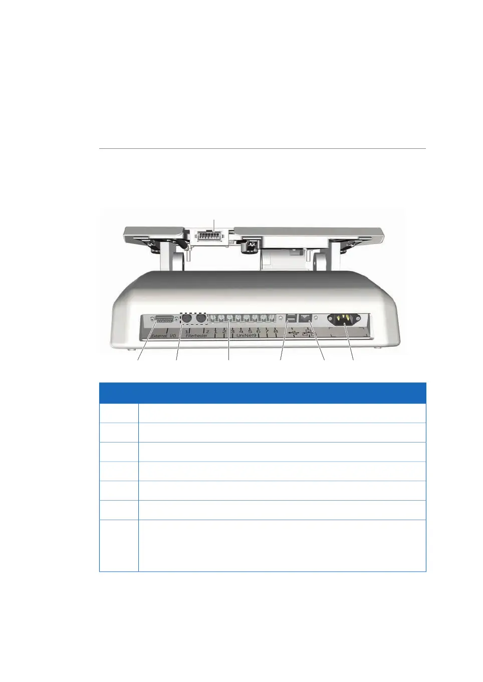
Rear view of the rocker
The illustration below shows the rear panel of the rocker.
DescriptionPart
15-pin D-sub connector, used for digital and analog I/O signals1
Filter heater connectors2
Tray connector3
UniNet-9 ports4
USB ports5
Ethernet connector6
Power connector
Note:
The rocker is fitted with internal electrical fuses that are not user-replaceable.
7
46 ReadyToProcess WAVE 25 Operating Instructions 29009597 AD
3 System description
3.2 ReadyToProcess WAVE 25 rocker
 Loading...