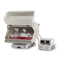
Illustration of Cellbag bioreactor
The illustration shows a general Cellbag bioreactor. The configuration of your Cellbag
bioreactor may vary from the configuration shown below.
DescriptionPart
pH bag sensor port, located on the underside of the bag1
Outlet vent filter with pressure control valve2
Inlet vent filter3
Addition port4
DO bag sensor port, located on the underside of the bag5
Cellbag rod6
Clave™ sampling port7
Addition port8
Addition/harvest port9
The inlet and outlet vent filters are distinguished by the pressure control valve
on the outlet filter.
Note:
ReadyToProcess WAVE 25 Operating Instructions 29009597 AD 59
3 System description
3.5 Cellbag bioreactor
 Loading...