Home
Gilbarco
Receiver
TRIND
Page 123 (T20607 Interconnection Diagrams, Sheet 2 of 4, Revision H)
Gilbarco TRIND - T20607 Interconnection Diagrams, Sheet 2 of 4, Revision H
131 pages
Manual
Save Page as PDF
To Next Page
To Next Page
To Previous Page
To Previous Page
Loading...
Appendix B - Cable Block Diagrams an
d Interconnects
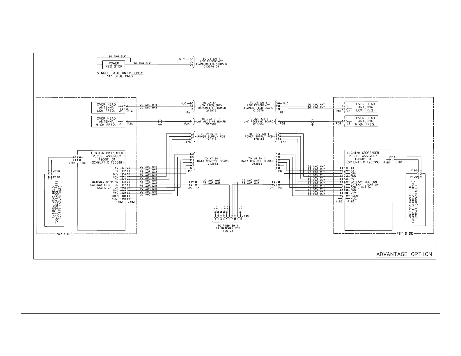
T20607 Interconnec
tion Diagrams, Sheet 2 of 4, Revision H
Page B-8
MDE-3664B
TRIND® Start-up, Service,
and Parts Manual · June 2013
T20607 Interconnection Diagrams
, Sheet 2 of 4, Revision H
122
124
Table of Contents
Main Page
Default Chapter
4
Table of Contents
4
1 Introduction
8
TRIND® Overview
8
About TRIND
8
How TRIND Works
9
Related Documents
10
Abbreviations and Acronyms
10
TRIND Kit Coverage
12
2 Important Safety Information
14
3 Systems Overview
18
Full Systems
18
Hand-Held Only Tag System Overview
21
4 Major Hardware Components
22
Card Cage Assemblies
22
T20229-G1 Card Cage Assembly
22
T20606-G2 Card Cage Assembly
23
T20606-G3 Card Cage Assembly
24
T20606-G5 Card Cage Assembly
25
Disassembly and Installation for MPD-3 Units with SID Displays
26
Disassembly and Installation for All MPD-3 Units
26
AC EMI Line Filter (Q10895)
27
R20600 and R20719 Transformers
27
T20138 and T20314 Power Supply Boards
27
Q13563 Data Control Boards
28
UHF Receiver Board (Q13564)
29
Q13579 Transmitter Board
30
T20128 and T20678 Gateway Boards
31
Card Cage Cable Harness (T20662-G2)
32
Full System TRIND Transmitter Cable (R20520-G1)
32
Full System TRIND RS-485 Communication Cable (R20525-G1)
33
Full System TRIND Power Supply Cables (R20763-GX)
33
Hand-Held TRIND System Ribbon Cable (M00507)
34
Hand-Held TRIND System Power Cable (M01366)
34
TRIND Overhead Antennas
35
Mobil Overhead Antenna Assembly (T20231)
35
Single-Loop Overhead Antenna Assembly (T20632)
38
UHF Antenna (Q13851-01 and Q13851-02)
42
Antenna Tuning Board (T20579-GX)
42
TRIND Option Doors with Antennas
42
Bezel Assemblies (T20616)
43
Advantage Wide Frame Option Door Assemblies
46
Advantage Narrow Frame Option Door Assemblies
48
Encore CIM Door Option Assembly
50
Eclipse Ovendoor Option Assembly
51
Light/Micro Reader PCB (T20446-G1, T20601-GX, M01580A001, and M01580A002)
52
M01218A001 and M01218A002 Light/Micro Reader PCB
53
Hand-Held Antenna PCB (T20143-G1)
54
TRIND Antenna PCA (T20524-G1)
54
System Cables
55
L/HF Antenna Cable (M00878)
55
Power and Data Option Door Cable (R20773)
55
R20437-G01 TRIND to CRIND Logic Cable (the Advantage Series and MPD-3)
56
M00515A002 TRIND to CRIND Logic Cable for Encore 500 and Eclipse
56
M001804A001 TRIND to CRIND Logic Cable for Encore 300
57
AC Power Cables (R20580 and M00811A001)
57
Full System Cable Connections on Legacy Advantage Series
58
Dispensers
58
Full System Cable Connections on MPD-3 Dispensers
59
Full System Cable Connections on the Advantage Series and MPD-3
60
Dispensers
60
Hand-Held System Cable Connections on the Advantage Series and MPD-3 Dispensers
61
Full System Cable Connections on Encore 500 Dispensers
62
Hand-Held System Cable Connections on Encore 500 and Eclipse Dispensers
63
Antenna Cable Pin-To-Pin Connections (M00878A001 and M00878A002)
64
Ribbon Cable Pin-To-Pin Connections (M00515A002)
64
Antenna Cable, Low Frequency Pin-To-Pin Connections (R20509-G1)
64
Light/Micro Reader Cables Pin-To-Pin Connections (R20519-G1, R20519-G2, and R20519-G3)
65
R20521-G1 and R20521-G2 Interface Micro Reader Cables Pin-To-Pin Connections
65
R20522-G1 Interface Hand-Held Antenna Cable Pin-To-Pin Connections
65
R20522-G2 Interface Hand-Held Antenna Cable Pin-To-Pin Connections
65
R20526 TI/RFID Dummy Load Transmitter Cable Pin-To-Pin Connections
65
R20437-G01 TRIND to CRIND Logic Cable Pin-To-Pin Connections
66
R20773-G2 Advantage Option TRIND Data and Power Cable Pin-To-Pin Connections
66
R20773-G2 Encore Option TRIND Data and Power Cable Pin-To-Pin Connections
67
T20662-G2 TRIND Card Cage Cable Harness Cable Pin-To-Pin Connections
67
5 System Accessories
68
ASC TRIND Tool Kit (K94577-01)
68
Kit Contents
68
Standalone Jumper Cables
68
Standalone Jumper Cable (R20602-G1) for LF/UHF Full System
68
Standalone Jumper Cable (R20602-G2) for Enhanced Gateway
70
Dummy Load Transmitter (R20526)
71
Co-Axial Cable Tool (Q13628-01)
71
Field Strength Sensor Board (Q13626-01)
72
Q13630-01 and Q13630-02 Test Tags
72
Tuning Tool (Q13631-01 and Q13631-02)
73
6 Procedures for Factory Installed TRIND
74
Positioning Overhead Antennas
74
7 Dispenser Setup
76
Addressing Dither Sync Address for LF/UHF Full System
76
Setting Baud Rate
77
Addressing Gateway/Enhanced Gateway Board
77
CRIND Address Table
79
Preparation for Tuning Antennas
80
Tuning Antennas
80
Tuning Single-Loop Antennas
80
Mobil Antennas
82
8 Testing and Troubleshooting
84
Status Indicators
84
Gateway Board (T20128)
84
Enhanced Gateway Board (T20678)
85
Data Control Board (Q13563)
86
T20601/M01560 Light/Micro Reader Boards
88
Isolating TRIND from CRIND
89
Tag Testing
89
Car Mounted Test Tags
89
Hand-Held Test Tags
90
Alternative Testing Using Laptop
91
Troubleshooting T20229-G1 PCB on Card Cage Assembly
92
Gateway PCB (T20128-G1)
93
Transmitter PCB (Q13579-01)
93
Dcb (Q13563-01)
94
TI/RFID Power Supply (T20138-G1)
94
Troubleshooting Flowcharts for T20606 Card Cage System
95
Field Problem Survey
99
9 Glossary
100
Appendix A - Radio Frequency Identification Defined
104
Overview
105
What Is RFID
106
Wireless Communication and Air Interface
107
Data Transfer Rate and Bandwidth
108
Range and Power Levels
109
Transponders/Tags
110
Basic Features of RFID Transponder
110
Powering Tags
111
Data Carrying Options
111
Data Read Rate
112
Data Programming Options
112
Physical Form
112
Costs
113
Reader/Interrogator
113
RF Transponder Programmers
113
RFID System Categories
114
Appendix B - Cable Block Diagrams and Interconnects
116
R20515 Cable Block Diagram, Revision F
116
R20516 Interconnect Diagrams, Sheet 1 of 3, Revision E
117
R20516 Interconnect Diagrams, Sheet 2 of 3, Revision C
118
R20516 Interconnect Diagrams, Sheet 3 of 3, Revision E
119
R20762 Cable Block Diagrams, Sheet 1 of 2, Revision J
120
R20762 Cable Block Diagrams, Sheet 2 of 2, Revision J
121
T20607 Interconnect Diagrams, Sheet 1 of 4, Revision H
122
T20607 Interconnection Diagrams, Sheet 2 of 4, Revision H
123
T20607 Interconnection Diagrams, Sheet 3 of 4, Revision H
124
T20607 Interconnection Diagrams, Sheet 4 of 4, Revision H
125
R20775 Cable Block Diagrams, Sheet 1 of 2, Revision D
126
R20775 Cable Block Diagrams, Sheet 2 of 2, Revision D
127
T20663 Interconnect Diagrams, Sheet 1 of 3, Revision C
128
T20663 Interconnection Diagrams, Sheet 2 of 3, Revision C
129
T20663 Interconnection Diagrams, Sheet 3 of 3, Revision C
130