MDE-3664B TRIND® Start-up, Service, and Parts Manual · June 2013 Page 5-5
Field Strength Sensor Board (Q13626-01) System Accessories
Field Strength Sensor Board (Q13626-01)
TRIND installation manuals and this document details the installation test for positioning of
the Field Strength Sensor Board during antenna field tuning.
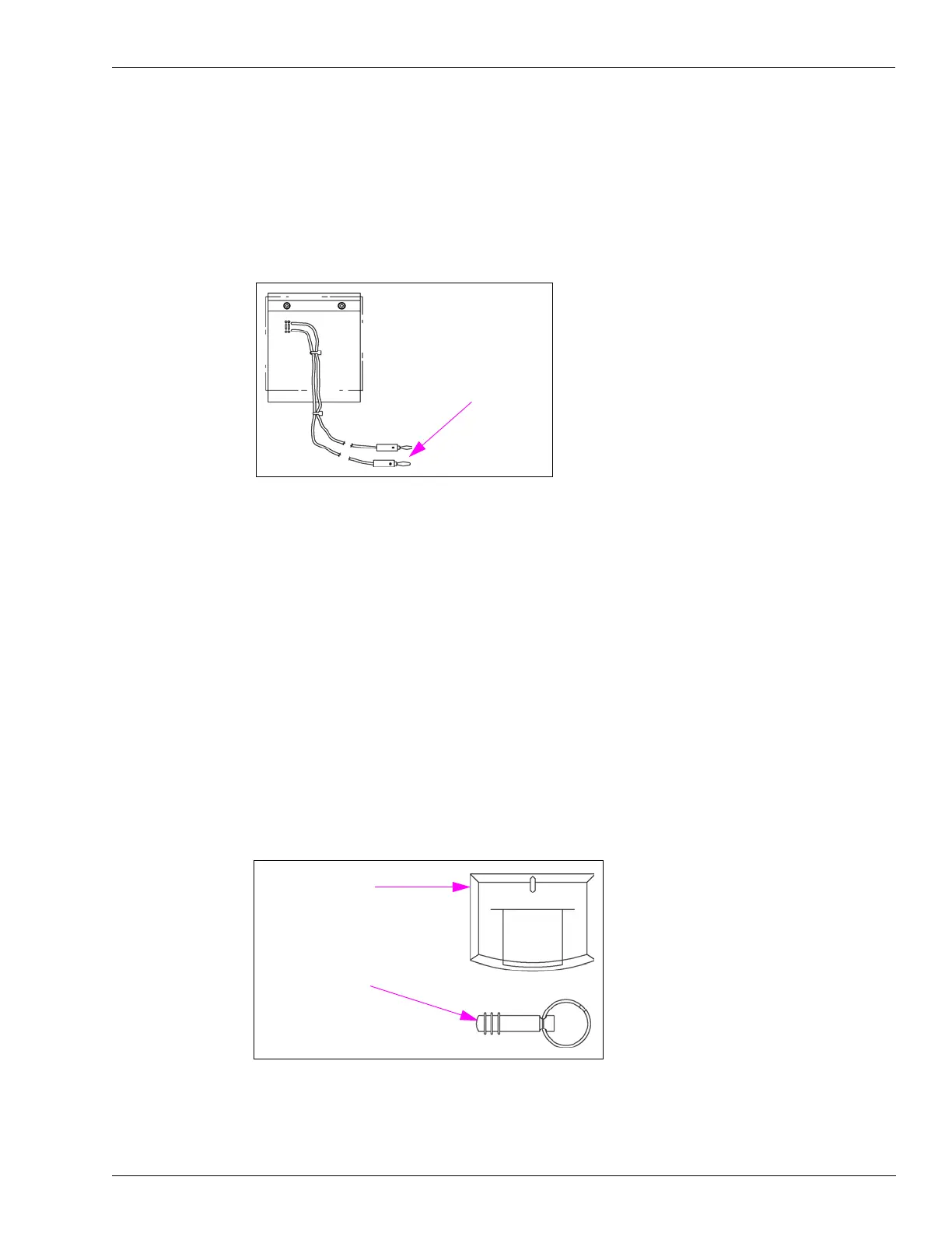
Figure 5-6: Field Strength Sensor Board
Set the multimeter to DC voltage. Connect the red and black leads of the standard multimeter
to the field strength sensor board leads. As the antennas are tuned by incremental adjustments
to the antenna’s variable inductor (similar to a tuning pot), voltage reading increases or
decreases. The field strength sensor board allows you to find the voltage peak, which is the
tuning target.
Q13630-01 and Q13630-02 Test Tags
Hand-held Test Tag (Q13630-01) simulates a hand-held transponder and has the appearance of
a key holder. Car-mount Test Tag (Q13630-02) simulates a customer’s car mounted
transponder. These tags are used to test operation of the TRIND system at installation.
Figure 5-7: Test Tags
Car-mount Test Tag
(Q13630-02)
Hand-held Test Tag
(Q13630-01)