MDE-3664B TRIND® Start-up, Service, and Parts Manual · June 2013 Page 7-5
Preparation for Tuning Antennas Dispenser Setup
Preparation for Tuning Antennas
Antenna tuning requires use of Field Strength Sensor Board supplied with the ASC TRIND
Tool Kit. For information on using Field Strength Sensor Board, refer to “Field Strength
Sensor Board (Q13626-01)” on page 5-5.
1 For units without G-SITE, put unit in ‘standalone’ mode. Refer to
“Standalone Jumper Cable (R20602-G1) for LF/UHF Full System” on page 5-1 and
“Standalone Jumper Cable (R20602-G2) for Enhanced Gateway” on page 5-3.
2 Restore power to unit(s).
3 After restoring power to the unit, verify that the unit is in “standalone” mode by observing that
the LEDs on the light board are flashing.
Tuning Antennas
Following sections provide instructions on tuning the Single-loop and Mobil antennas.
Tuning Single-loop Antennas
Perform the following steps in to tune a Single-loop Antenna.
1 Locate the access port for the tuning pot in the overhead antenna connection box on Side A.
Note: Use Tuning Tool (Q13631-XX) from the ASC TRIND To
ol Kit to make pot adjustments.
For instructions, refer to MDE-3640 ASC TRIND Tool Kit. Hex end of tuning tool
matches hex shape of tuning pot.
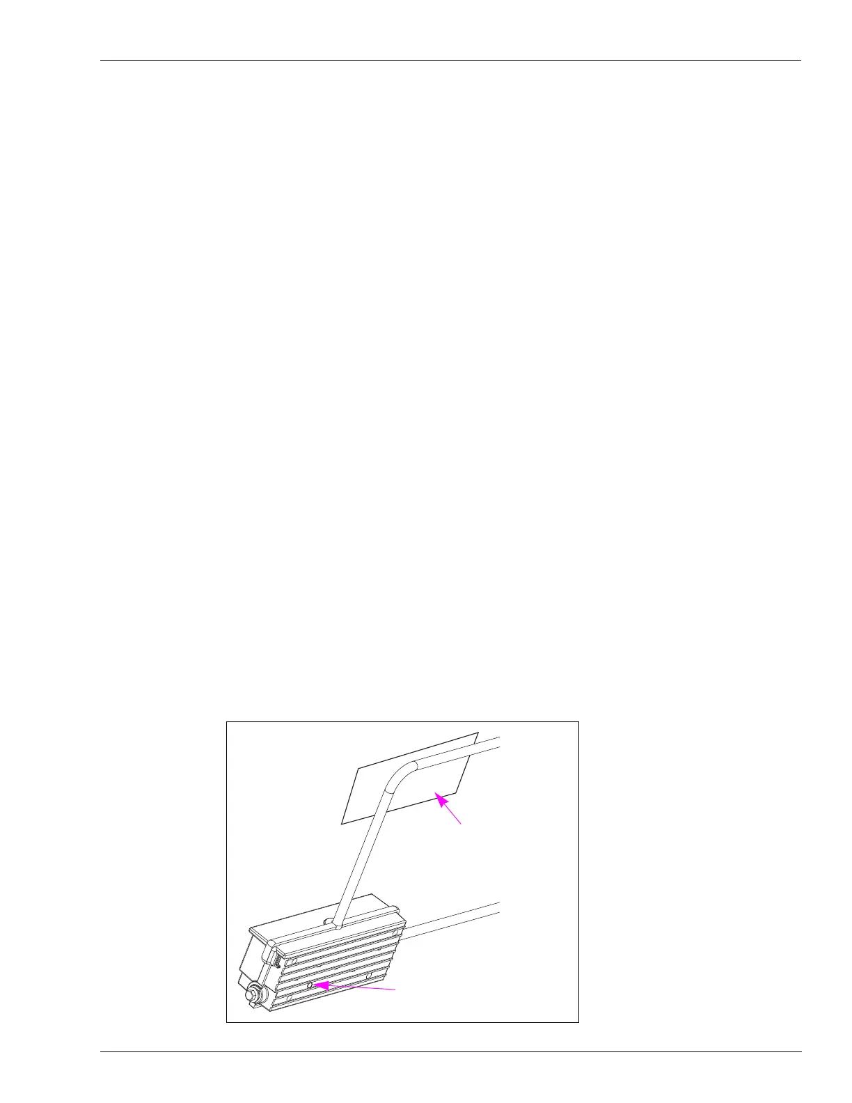
2 Lay field strength sensor on the antenna as shown in Figure 7-4. Exact location is not critical.
Figure 7-4: Field Strength Sensor Positioning
Tuning Pot Access Port Location In
Overhead Antenna Connection Box
Field Strength Sensor
Underside of Antenna View