MDE-3664B TRIND® Start-up, Service, and Parts Manual · June 2013 Page 4-5
Card Cage Assemblies Major Hardware Components
T20606-G5 Card Cage Assembly Parts List
Following table lists the T20606-G5 Card Cage Assembly parts:
Item Description Part Number
1 TRIND Gateway PCB T20128-G3
2 Circuit Board Support Q10651-16
3 TRIND PCB Bracket M00624A001
4 ETSI DCB Q13563-07
5 Radio PCB Shield R20545-G1
6 PCB Insulator Board R20590-01
7 Low Frequency Transmitter Module Q13579-01
8 24 VAC Transformer R20719-G1
9 Recessed Power Receptacle R20206-G14
10 10 A EMI Filter Q10895-01
11 TRIND PCB Shield Bracket M00621A001
12 Regulator PCB Shield T20198-01
13 Regulator PCB T20314-G1
Disassembly and Installation for MPD-3 Units with SID Displays
In some older installations, a screw and two nuts were installed under the Card Cage on Side B
of a unit. This causes the installed Card Cage to rest at an angle, higher on Side B. This
hardware must remain in place to prevent contact between the Card Cage and the SID boards
when the bezel door is closed.
Disassembly and Installation for All MPD-3 Units
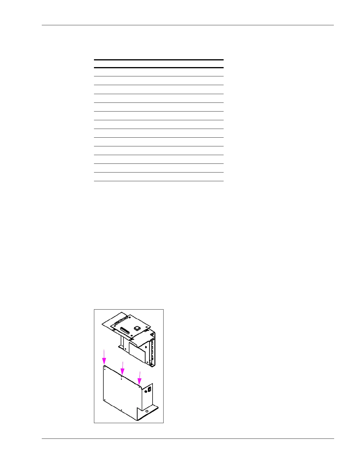
In field retrofits, the TRIND units top (center) screw from the Card Cage was removed, and
replaced by tie-wraps at either side after the Card Cage was installed in the cabinet. The Card
Cage can only be removed or installed when separated into two pieces (see Figure 4-5).
Figure 4-5: Screw and Tie-wrap Locations